Plant Engineering - What's New?

Service Pack 2 2023 (V 2802)
Eccentrically inserted pipes
The insertion of a pipe is often done by placing both pipes on the ground and then cutting/welding them together. Accordingly, the inserted pipe must be able to have a distance 0 from the outer wall of the larger pipe. However, the previous implementation in HiC 2023 (V 2800 and 2801) forces a distance of at least the wall thickness of the larger pipe.
For this particular use case, the function Align component connection tangentially has been adapted in SP2. Instead of the internal distance to the outer wall, the distance to the outer wall must now be specified.
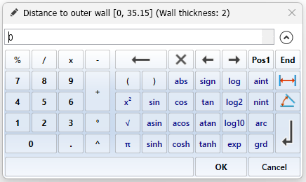
In addition to the sensible input range, the wall thickness of the larger pipe is now displayed in the title line of the input window. So if you want to emulate the previous behaviour (A) and assign an internal distance of 0 to the inserted pipe, enter the wall thickness as the distance.
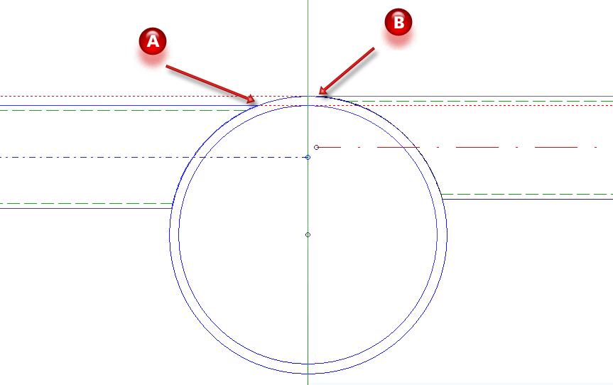
(A) up to HiC 2023 SP1: Outer diameter of inserted pipe tangential to inner diameter of main pipe
(B) from HiC 2023 SP2 onwards: Outer diameter of inserted pipe tangential to outer diameter of main pipe, constructive distance 0.1 mm
![]() Please note:
Please note:
To avoid unaesthetic protrusions on the inserted tubes, the function ensures a minimum constructive distance of 0.1mm.
Pipe parts: Prevent seals
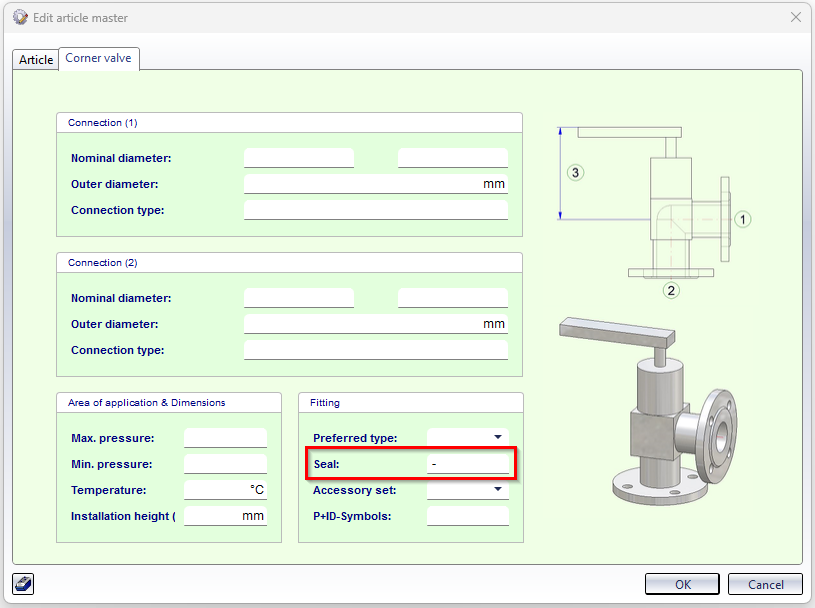
The insertion of seals and gaskets can be prevented via the article master of a corresponding part. To do this, set the attribute value for Seal in the article master to the value - (minus). This ignores seal settings at all connections of the part, i.e. no seals are set. This also applies when other parts are connected to this part.
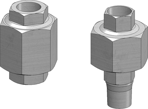
Example:
Nozzles for DIN EN 1092-1
With SP2, new variants are available for nozzles:
- STUTZEN_FL_PN10.vaa
- STUTZEN_FL_PN16.vaa
- STUTZEN_FL_PN25.vaa
- STUTZEN_FL_PN40.vaa
These are revisions of the variant STUTZEN_FL1.vaa, which still refers to the old standard DIN 2630.
The following seal variants have been added to the parts inventory to match the new nozzles:
- DIN1514-1-PN10.vaa
- DIN1514-1-PN16.vaa
- DIN1514-1-PN25.vaa
- DIN1514-1-PN40.vaa
These variants are summarised in the list file nozzles_1092-1.lst.
New malleable cast iron fittings
The stock of Georg Fischer malleable cast iron fittings according to standard EN 10242 has been extended by two further variants:
- GF10242_S330.VAA und
- GF10242_S331.VAA.
Welding neck flanges acc. to EN1092-1-11-C/D
The parts inventory for Plant Engineering has been expanded with SP2 to include the following variants:
|
Flanges with notch |
Flanges with groove |
|---|---|
|
EN1092-1-11-C-PN10.vaa EN1092-1-11-C-PN16.vaa EN1092-1-11-C-PN25.vaa EN1092-1-11-C-PN40.vaa EN1092-1-11-C-PN63.vaa EN1092-1-11-C-PN100.vaa EN1092-1-11-C-PN160.vaa EN1092-1-11-C-PN250.vaa EN1092-1-11-C-PN320.vaa EN1092-1-11-C-PN400.vaa |
EN1092-1-11-D-PN10.vaa EN1092-1-11-D-PN16.vaa EN1092-1-11-D-PN25.vaa EN1092-1-11-D-PN40.vaa EN1092-1-11-D-PN63.vaa EN1092-1-11-D-PN100.vaa EN1092-1-11-D-PN160.vaa EN1092-1-11-D-PN250.vaa EN1092-1-11-D-PN320.vaa EN1092-1-11-D-PN400.vaa |
Also new are the following variants:
|
EN1092-1_Insertring.vaa |
Insert ring to connect two grooved flanges to each other. The insert ring is classified as a valve and behaves like an intermediate flange valve when bolted together.
|
|
Seals |
|
|
DIN2691_grooved_gasket.vaa |
|
|
EN1541-1_FLAT_GASKET.VAA |
|
|
EN1541-2_SPIRAL_GASKET.VAA |
The thickness of the gasket represents the thickness after installation. |
Flanges up to and including PN63 have a seal according to EN1541-1 in their attribute DICHTUNG (Seal). The flanges from PN100 onwards, on the other hand, have the seal according to EN1541-2.
All new variants are summarized in the list file EN1092-1-11-C+D.lst.
New part attribute "Pipe clamp support type"
As of SP2, the attribute Pipe clamp support type - attribute name PIPE_SUPPORT_TYPE - can be assigned to pipe clamps in the part attributes.
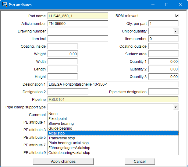
By assigning this attribute, different pipe clamp types can be displayed in ROHR2.
BOM tables - Line breaks
Three BOM tables can be generated automatically in isometries and pipe spool drawings.
- Pipe BOM,
- Pipe length list and
- Weld seam list.
The cells of these tables are filled from the attributes of the parts or by fixed default values. You can define the width of such a cell in the Configuration Editor.
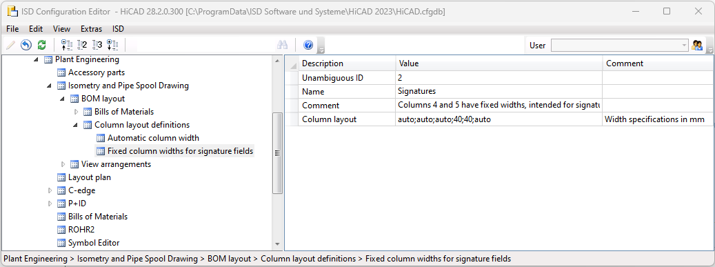
On the other hand, this can also be done directly in the isometry or pipe spool drawing settings if you deactivate the Column layout option.
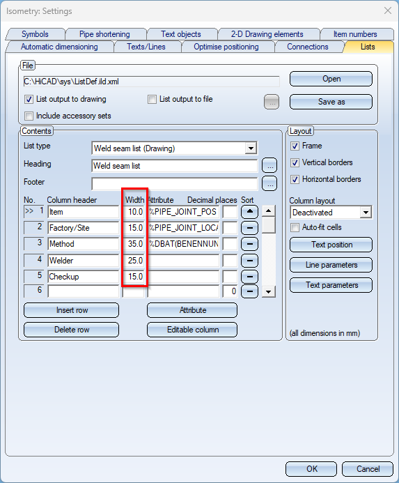
Previously, texts that were too long for a table cell were automatically shortened by HiCAD. The shortening was marked by an ellipsis (...). As of HiCAD 2023 SP2, texts that are too long are wrapped.
(1) before HiCAD 2023 SP1, (2) as of HiCAD 2023 SP2
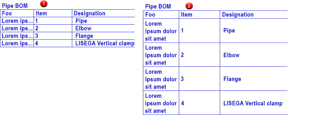
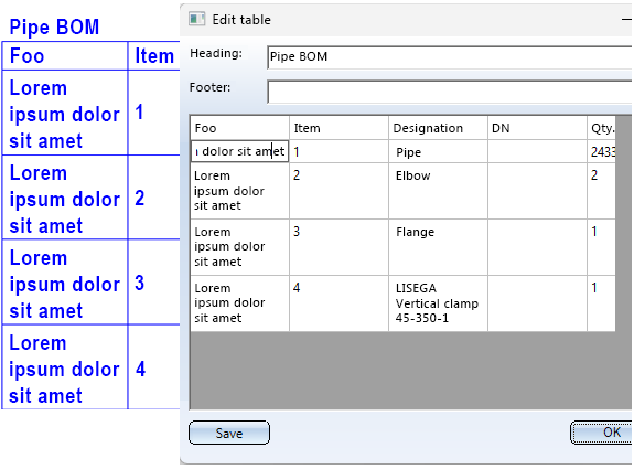
However, the automatic line break is only applied to BOMs that appear on the drawing. BOMs that are saved in files contain the full text without shortening and without additional line breaks.
If you edit the BOM manually, no line breaks are inserted. If the lines become too long, the text is shortened. When manually editing with the Edit list function, you have the option of forcing a line break with <CTRL>+<INPUT>.
Part insertion - Check pipe class for reference parts
If a pipeline with a pipe class is active when selecting the Part insertion  function, then the functions
- Select reference part and
- Select reference part depending on part type
a message is displayed if the pipe class of the selected reference part does not match the pipe class of the pipeline.
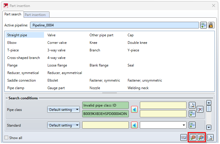
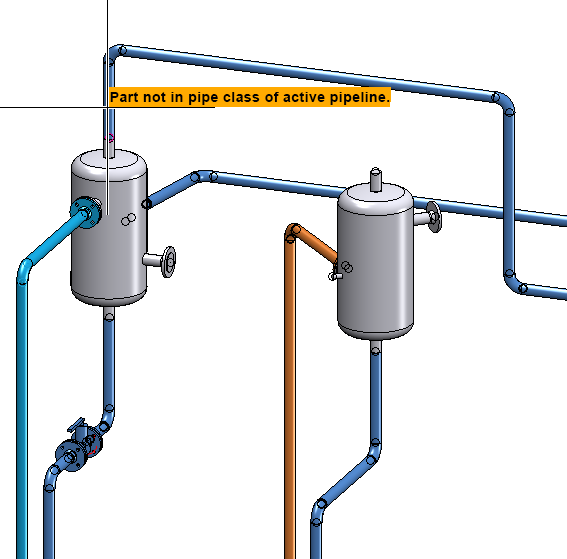
However, the part can still be selected as a reference part.
Isometry - Set reference coordinate system per pipeline
Normally the world coordinate system of the layout plan is used as the reference coordinate system for determining coordinates in the isometries and pipe spool drawings. However, you can give pipelines a reference coordinate system that is taken into account when generating isometries and pipe spool drawings, e.g. when displaying coordinates in annotation tags.
To do this, use the Set reference CS for isometry function (Plant Engineering > Isometry/Pipe Spool Drawing > Ref...  ).
).
Previously, a reference coordinate system set with this function was valid for all pipelines in the drawing. It was not possible to restrict this to individual pipelines.
For SP2 this function has been adapted so that it sets the reference coordinate system of individual pipelines.
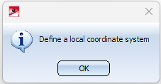
The prerequisite is that a local coordinate system exists in the layout plan. For this purpose you can use, for example, the function Plant Engineering > Settings > Settings  > Set on connection
 . If no local coordinate system is defined, a corresponding message appears:
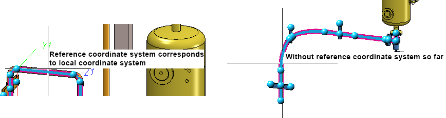
If a local coordinate system exists, you are prompted to select a pipeline when you start the Ref... function. you will be asked to select a pipeline.
As soon as the graphic cursor is moved over a pipeline, it is displayed directly at the cursor whether the pipeline already has a reference coordinate system.
One of the three following messages can be displayed:
- Without reference coordinate system so far
By clicking on the pipeline the local coordinate system is taken over as the reference coordinate system of the pipeline. - Reference coordinate system corresponds to local coordinate system
- Reference coordinate system deviates from local coordinate system
The local coordinate system has been changed subsequently.
In the dialogue of the isometry as well as the pipe spool drawing generation it is marked by the  symbol whether a pipeline has a reference coordinate system.
Likewise, the function Delete reference CS for isometry  has been adjusted, i.e. the function deletes the reference coordinate systems of individual pipelines. As soon as the graphic cursor is moved over a pipeline, you are informed directly at the cursor whether the pipeline already has a reference coordinate system. The messages are the same as when setting a reference coordinate system.
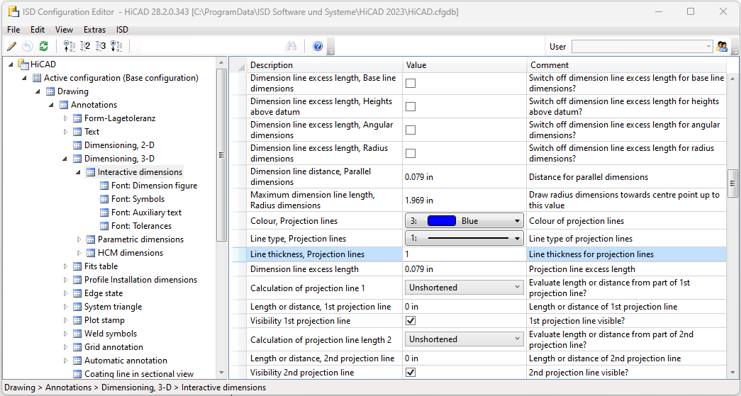
Display of projection lines in isometry and pipe spool drawing
To display the projection lines in the isometry and in the pipe spool drawing, use the settings in the Configuration Editor at Drawing > Annotations > Dimensioning, 3-D > Interactive dimensions.
PartDataAutoSync / DBPlantDataImport
PartDataAutoSync - Deleting articles
The tool PartDataAutoSync deletes articles for which there is no sub-type in the variant file. If the deletion fails, the message Data AutoSync incomplete is displayed directly in the dialogue. A list of the articles for which deletion failed appears in the log, e.g.:
Unsynchronized articles:
Deletion of article failed: HELIOS:\\B00XIKCF0R3DD0000040F0_0
Check of Consistency Between Archive File and HELiOS Article
In both PartDataAustoSync and DBPlantDataImport you can now get an overview of how the sub-types of an archive file (i.e. VAA or PAA) are displayed as linked articles in HELiOS.
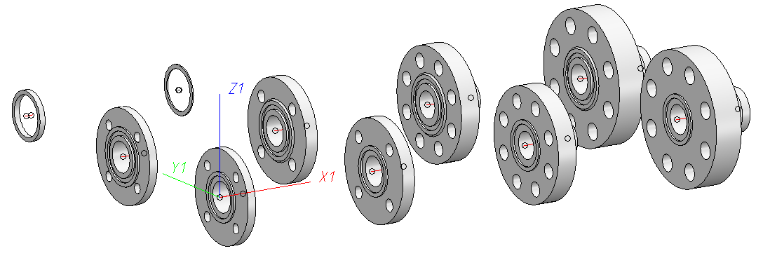
For a concrete variant, there is usually a linkage structure that looks something like this:
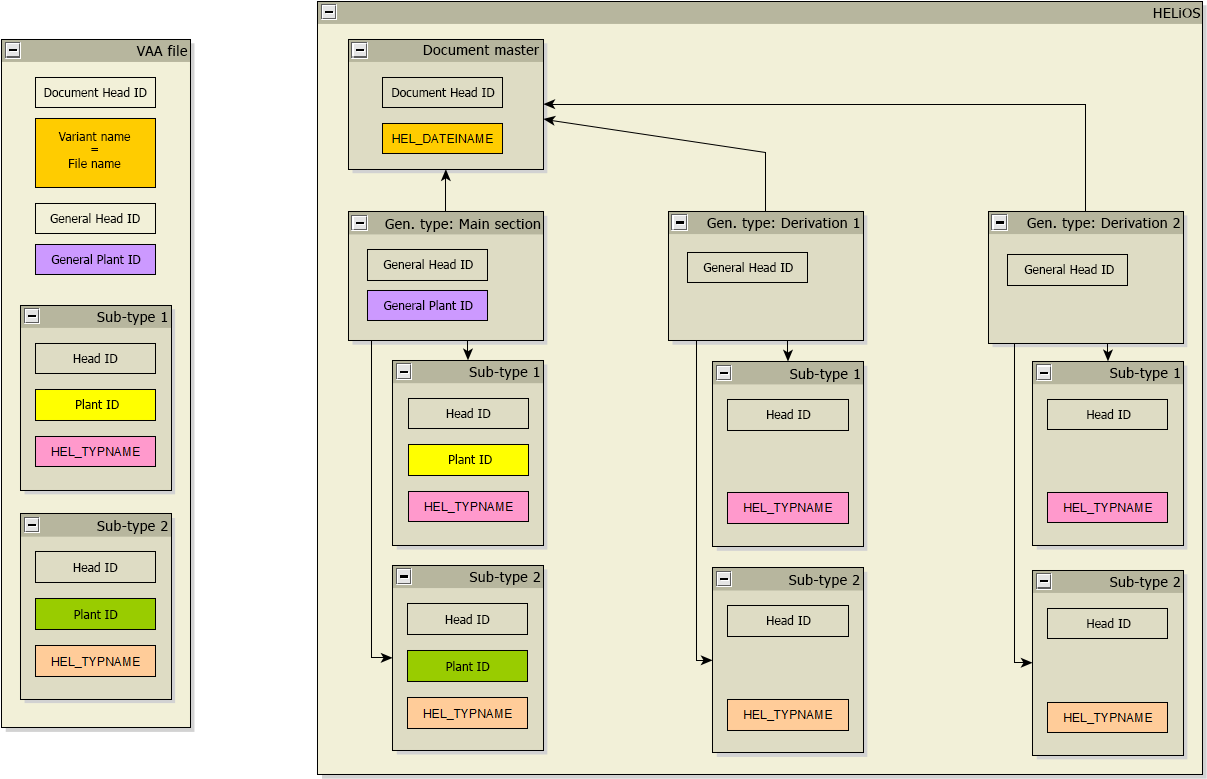
So in the VAA file several sub-types are defined, which are identified by an article type, which in turn is mapped in HELiOS to the attribute HEL_TYPNAME.
When the VAA file is transferred to HELiOS, the following are created:
- a document master,
- an article master for the general type and
- one article master for each sub-type.
These articles together with the general type form the main section and are connected to each other by links. The articles are characterised by the fact that identifiers are stored for them, which can be found again in the VAA file. These are the Plant IDs.
In addition, further sub-sections may have been created with the HELiOS function Derive variant  .. These are also linked to the document master, but have no unique identifiers. Instead, these items can be assigned to the sub-types via the item type.
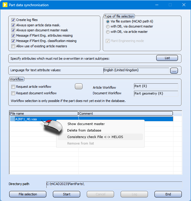
To get an overview of the current state of this linkage structure before matching a variant, use the function Consistency check File <-> HELiOS. This function is available in the part data sync in the context menu of the file selection.
After executing the function, the file compare_file_to_HELiOS_protocol.txt. can be found in the HiCAD Temp directory. In addition, the Notepad opens automatic and displays the contents of the file. The content looks something like this:
|
09.01.2023 09:14:12: File: A2RF1_100.vaa
General type: HELIOS:\\B00A137W6LK2UT00008TXJ_0 Status: Sub-section derived via HELiOS Article types of sub-types for which no article exists: 300 Articles without article type: none Articles with article type that does not exist in the archive: HELIOS:\\B00A137W6LK2UT00008TXK_0 HELIOS:\\B00A137W6LK2UT00008TXN_0 Articles that could not be accessed: none
General type: HELIOS:\\B00A137W6LK2UT00008TXX_0 Status: Sub-section derived via HELiOS Article types of sub-types for which no article exists: 300 Articles without article type: HELIOS:\\B00A137W6LK2UT00003NR8_0 Articles with article type that does not exist in the archive: HELIOS:\\B00A137W6LK2UT00008TXY_0 HELIOS:\\B00A137W6LK2UT00008TY1_0 Articles that could not be accessed: none
General type: HELIOS:\\B00DH4XULBEB5J000004FY_0 Status: Error: Main section with additional articles Article types of sub-types for which no article exists: 300 Articles without article type: none Articles with article type that does not exist in the archive: HELIOS:\\B00DH4XULBEB5J000004G0_0 HELIOS:\\B00DH4XULBEB5J000004G3_0 Articles that could not be accessed: none |
At the top of the file, the date and time of the check is shown, followed by the VAA file that was checked. Then follows one paragraph for each derived section. So in the above example there are three derivation sections. For each section, the article of the general type is first output as a HELiOS link. This is followed by the status of the section, i.e. main or sub-section.
Next, it is listed whether there are deviations from the ideal state in this section, such as:
- Article types of sub-types for which no article exists.
This is OK and occurs if there are additional sub-types in the VAA that have not yet been transferred to HELiOS. - Articles without article type.
Articles that do not have an article type are linked to the general type. Either this has been deleted or an invalid link has been created. In either case, this is an error. - Articles with article type that does not exist in the archive.
Usually occurs when a sub-type has been deleted from the archive. This is not an error. However, it can also occur if a link has been created to an article that does not come from the VAA file but has an article type. This would be an error. - Articles that could not be accessed.
Errors when accessing the article, this first says nothing about the link structure.
Part data sync - Restoring the main section for derivation
It can happen that the main section of a variant is no longer in the database, usually because articles were accidentally deleted.
Until now, the only way to restore this main section was to remove the variant from the database and match it again. This is particularly annoying if further derivations have already been created for the variant via the HELiOS function
Derive variant , because these are also removed in the process and have to be created again.
As of SP2, the part data sync restores the main section if it could not be found.
Service Pack 1 2023 (V 2801)
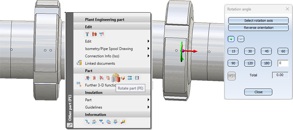
Rotate part: Reverse orientation
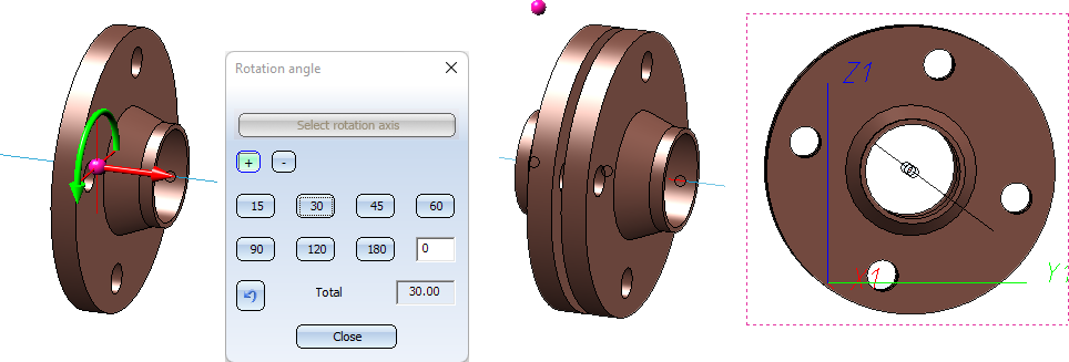
The function Rotate part  has been extended. You have now the option to reverse the orientation of a part.
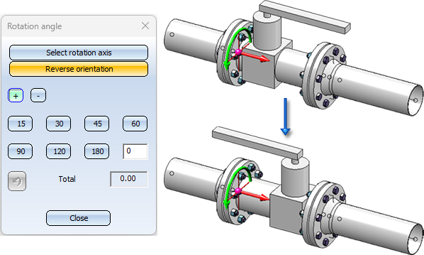
However, this is only possible for parts that have two connections and could be placed on a straight piece of guideline, i.e. parts for which a rotation cannot lead to inconsistencies with the possibly underlying guideline.
Check article numbers of pipelines
As of SP1, HiCAD 2023 offers the possibility to check whether all pipelines in your drawing have an article number and whether this number is unique.
For this purpose, the function
 Check article numbers of pipelines
is now available at Plant Engineering > Pipeline Tools > Coll...> .... After the check has taken place, a dialogue is displayed with information about the status of the pipelines. By clicking on an article number, the corresponding pipeline can be selected directly.
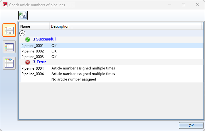
The result list can be output as a CSV file.
Divide pipeline into connection components
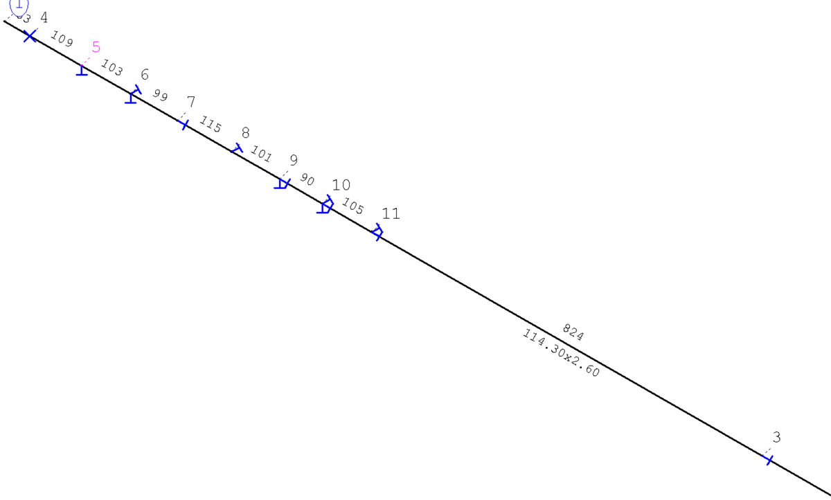
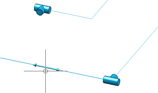
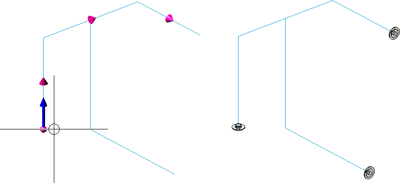
Sometimes it can accidentally happen that one pipeline has been constructed which should actually consist of several pipelines. That is, the pipeline consists of several so-called connection components. The following image shows such an example:
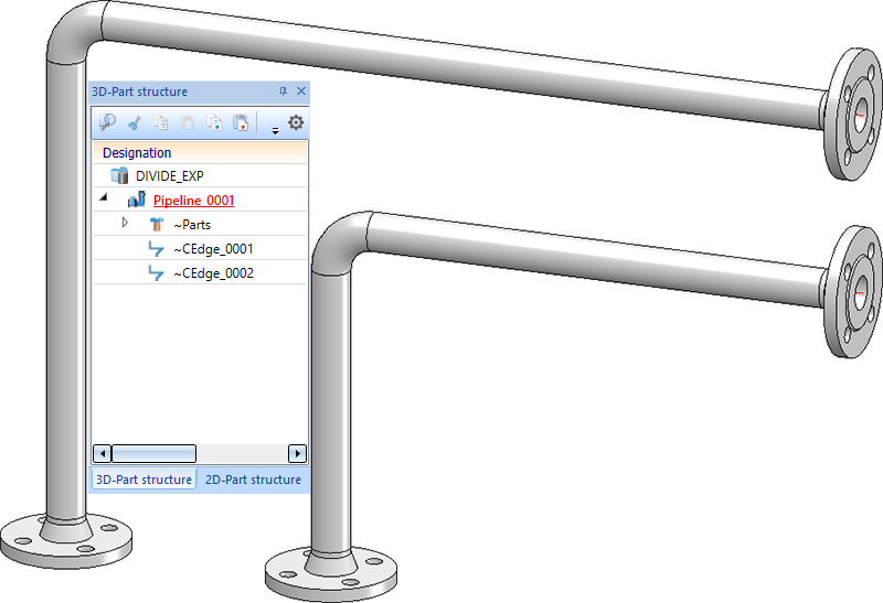
The Divide pipeline  function has not supported the division of such a pipeline so far. As of HiCAD 2023 SP1, the system checks whether the pipeline to be divided consists of several connection components and indicates this - if so - at the cursor by a corresponding message.
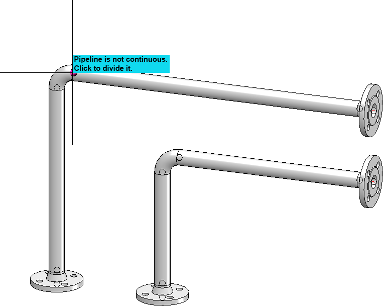
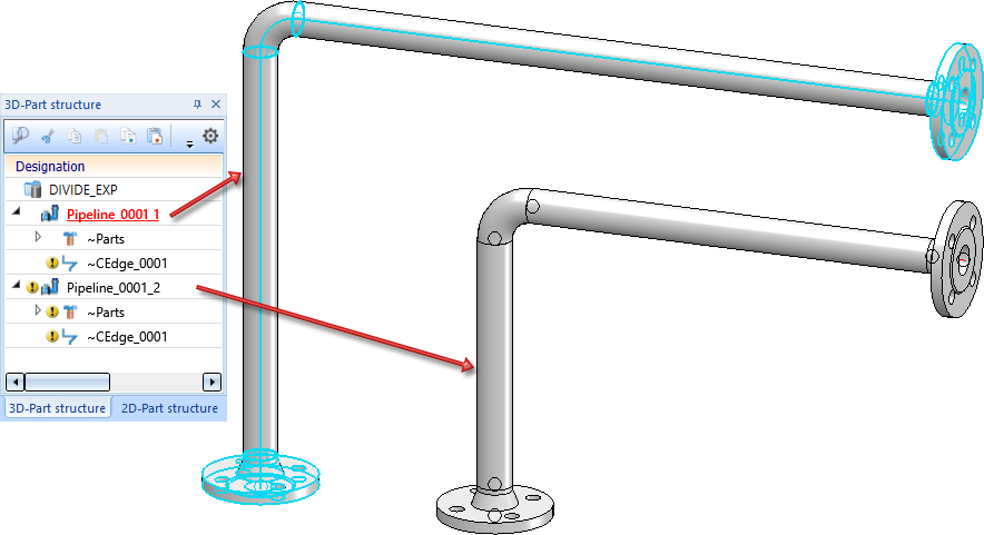
If the pipeline is to be divided, it is sufficient to click on the pipeline and to answer the subsequent query with Yes.
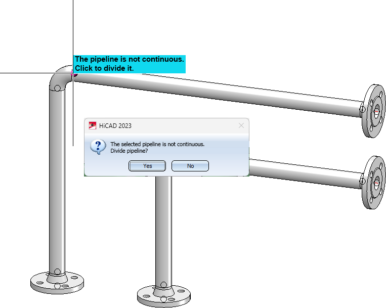
Each connection component will then become a separate pipeline.
Set weld seam gaps manually
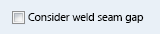
At Plant Engineering > Pipeline Tools > Change > ...you can find the new Add/remove gap  function. With this function weld seam gaps can be added to or removed from a pipeline. The behaviour of the function depends on whether the Consider weld seam gaps checkbox is active in the Plant Engineering settings on the weld seam gaps tab.
Consider weld seam gaps is activated
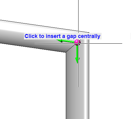
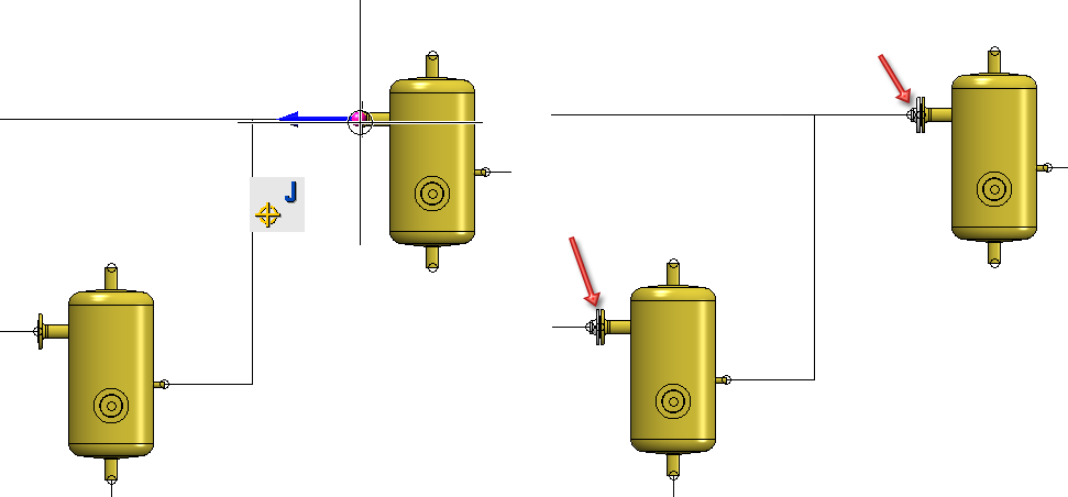
After calling the function, HiCAD prompts you to select a connection. If you move the cursor near a weld seam, it will be highlighted (1). To select the connection for editing, press the left mouse button. HiCAD then prompts you to determine the way in which a gap is to be added or removed. For this purpose, selectable graphic elements are displayed in the drawing (2).
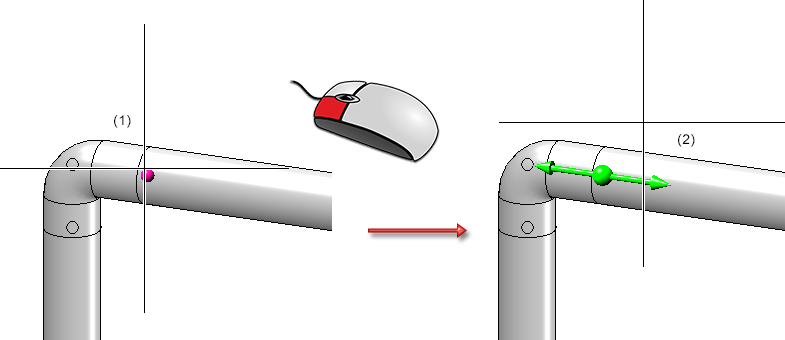
In the example shown you can make the connection
- on the left side,
- centrally, or
- on the right side.
These options are pointed out to you when you move the cursor over the respective graphic element.
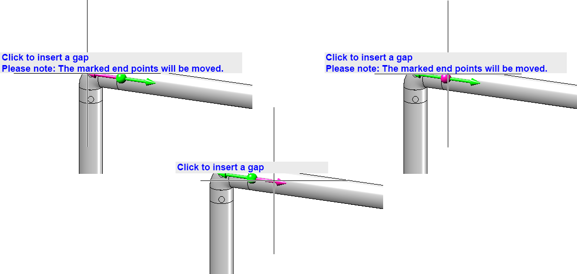
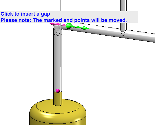
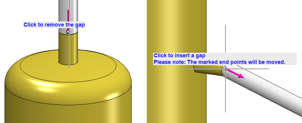
If end points of the pipeline are moved by adding or removing a gap, this is indicated. In the example shown above (left) this hint appears because the pipeline is connected to a vessel.
With a right-click a context menu can be activated, which can also be used to deactivate the display of the information texts.
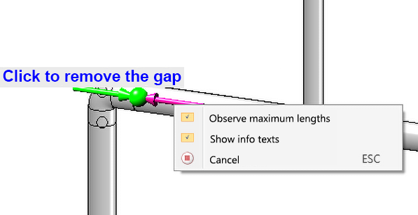
In addition, the consideration of maximum lengths can also be deactivated here, but this should be unnecessary as a rule.
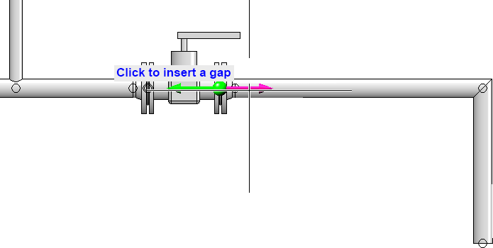
After you have edited a gap (or pressed ESC), you will be asked to select another connection. In the example, we select the same connection that we have previously edited.
From the direction of the arrows you can see directly whether a gap is inserted or closed.
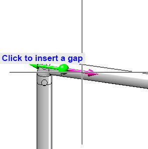
At mitres, the graphic elements are drawn according to the direction of the pipes involved.
The position of components such as vessels and pumps is not changed by the function. Accordingly, only one possible action is offered here.
Consider weld seam gaps is deactivated
If the Consider weld seam gaps option is deactivated in the Plant Engineering settings, then you still remove existing gaps. Instead of inserting a gap, however, you are offered to create a space in the pipeline. You are no longer limited to welded joints. You define the width of the space by entering a value in the calculator.
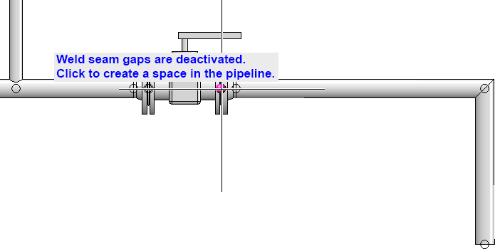
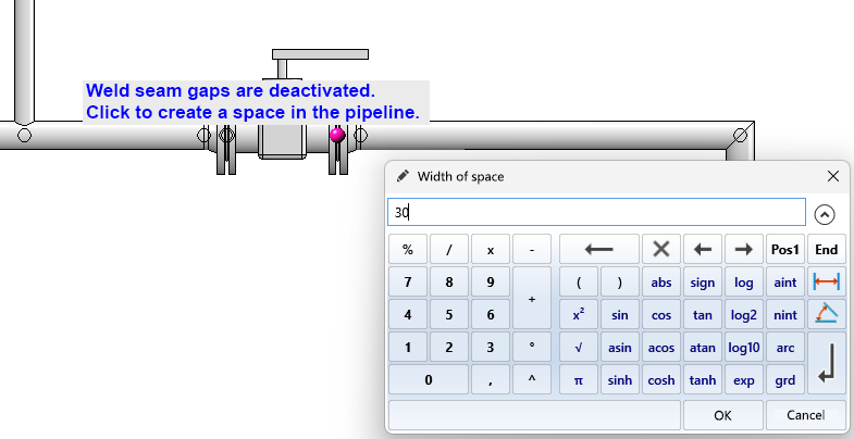
Please note that such a space cannot be closed again with this function, as it interrupts the pipeline connection and - unlike a weld seam gap - does not establish a relationship between the parts of the pipeline. To close the space, use the function Close spaces. Or use the function Change route to drag the now free end point to another position.
VOSS-ZAKO flared flanges
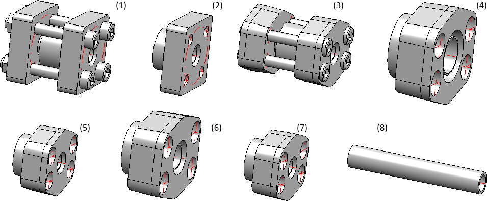
The part inventory for Plant Engineering has been extended by ZAKO flared flanges from the manufacturer VOSS. The following variants have been added:
|
1 |
Square pipe flange connection - high-pressure series |
Z-TTO_Q-FLANSCHVERBINDUNG_HD.VAA |
|
2 |
Square flange connection - high pressure series |
Z-TPO_Q-NUTFLANSCH_HD.VAA |
|
3 |
Pipe-flange connection SAE - standard series |
Z-TTO_SAE-FLANSCHVERBINDUNG_HD.VAA |
|
4 |
Connecting flange connection SAE - high pressure series with reducer |
Z-TPO_SAE-NUTFLANSCH-HD-RED.VAA |
|
5 |
Connecting flange connection SAE - high pressure series |
Z-TPO_SAE-NUTFLANSCH-HD.VAA |
|
6 |
Connecting flange connection SAE - standard series with reducer |
Z-TPO_SAE-NUTFLANSCH-RED.VAA |
|
7 |
Connecting flange connection SAE - standard series |
Z-TPO_SAE-NUTFLANSCH.VAA |
|
8 |
Straight pipe according to EN10305, the sub-types of which are matched to the new VOSS-ZAKO variants. |
Z-TPO_PIPE_10305.VAA |
 The nominal diameters in the manufacturer's specifications have been adapted to the usual nominal diameters.
Welding necks and handling of loose flanges
New part type and variants
In pipeline planning there is the situation that loose flanges can be inserted once as flanges and once as fasteners. This leads to problems, especially in interaction with HELiOS, because in the worst case two articles have to be created for one part, one as a flange and one as a fastener.
Therefore, existing loose flanges N2642_LF_R1.VAA and N2642_LF_R2.VAA classified as fasteners are additionally offered classified as flanges as of SP1.
|
Series |
Variant * |
Standard designation |
|---|---|---|
|
1 |
N2642_LFC_R1.VAA |
N2642 R1 |
|
2 |
N2642_LFC_R2.VAA |
N2642 R2 |
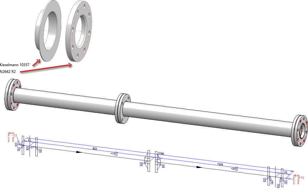
These loose flanges were previously used as fasteners for welding necks, which were previously designed as flanges.
As of HiCAD 2023 SP1, there are now welding necks as a new part type. On the one hand, these are designed for interaction with the regular loose flanges. On the other hand, they support functionalities that are otherwise found in flanges. One example is the automatic setting at free ends and the automatic counterflanging.
The part families KM10357_WN_DIN.VAA and ROFI10357_WN_ISO.VAA (previously classified as flanges) are available classified as welding necks:
|
Variant * |
Standard designation |
|
|---|---|---|
|
KM10357_WNC_DIN.VAA |
Kieselmann 10357 |
|
|
ROFI10357_WNC_ISO.VAA |
RO-FI 10357 |
contains all sub-types of the modelled welding neck |
|
ROFI10357_WNC_ISO_R1.VAA |
RO-FI 10357 R1 |
each contains a share of the sub-types from ROFI10357_WNC_ISO.VAA |
|
ROFI10357_WNC_ISO_R2.VAA |
RO-FI 10357 R2 |
|
* The C in the file name of the adapted variants stands for collar (as short form of weld neck collar). The C in the file name of the adapted parts therefore has an additional C in the name (for collar as short form of weld neck collar).
The loose flanges of Series 1 fit the variant ROFI10357_WNC_ISO_R1.VAA. The loose flanges of Series 2 fit the variants ROFI10357_WNC_ISO_R2.VAA and KM10357_WNC_DIN.VAA.
Connection type attribute
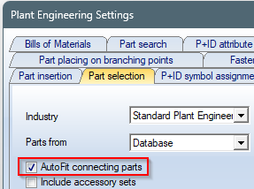
Welding necks can provide loose flanges for their connection type. As there is no part type loose flange, it was defined for welding necks that a loose flange is meant if the part type ID for flanges is used in the connection type, i.e. 5100010. If welding necks are to be inserted with the loose flange from the connection attributes, the AutoFit connecting parts option must be activated on the Part selection tab of the Plant Engineering Settings dialogue window.
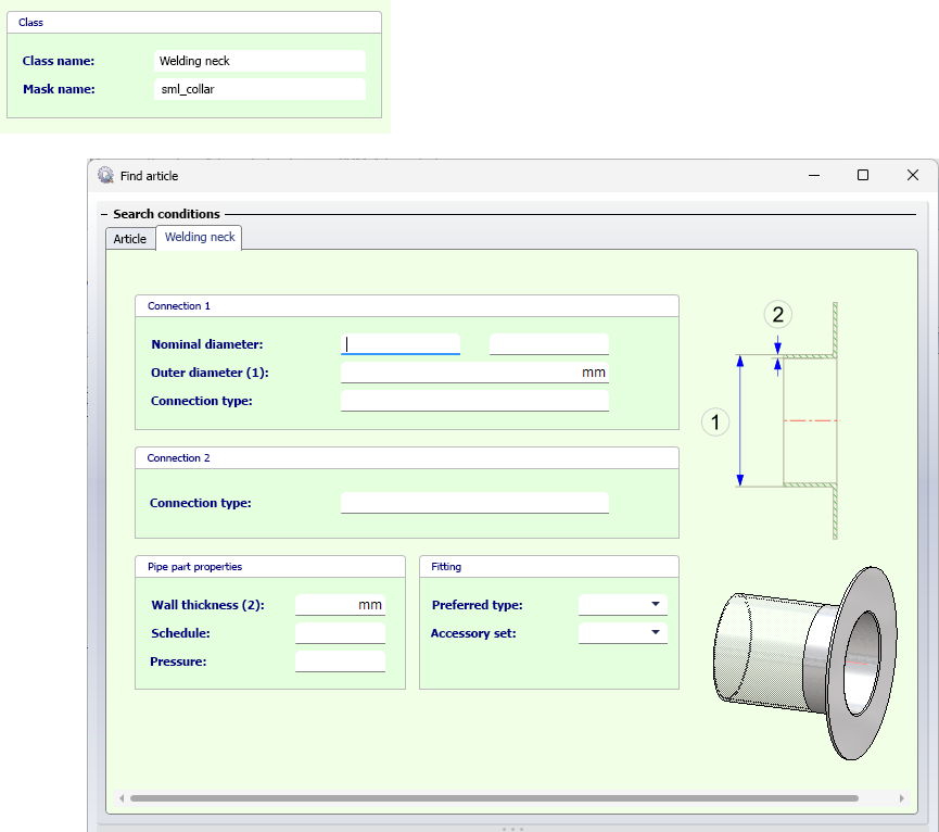
To model your own welding neck, please read the information in the topics Part Type: Welding Neck or Variant for Part Type: Welding Neck.
Standards in the connection type attribute
As of HiCAD 2023 SP1, a part type ID can be used in the connection type definition without additionally specifying the standard. For welding neck flanges, you can therefore specify that you want to automatically install a loose flange without specifying the standard. If the loose flange is not unique, you will be offered a corresponding search mask (catalogue or HELiOS). However, if you use HELiOS, you must first update HELiOS for Plant Engineering as described in the next point. If you use the catalogue for part selection, you may have to use the tool vartocat.exe in the HiCAD exe directory to be able to use the new part type.
New part type "Welding neck"
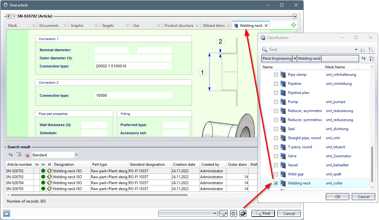
In HiCAD 2023 SP1, a new part type for Plant Engineering and thus a new article class is available in the form of the Welding neck.
If you use HELiOS, you must inform HELiOS of the new classification for welding neck flanges. This is done via the programme DBPlantDataImport.exe, which you will find in the HiCAD exe directory. There you click on the button Update HELiOS for Plant Engineering. Afterwards you can use the HELiOS search mask in your HELiOS Desktop.
Function adjustments
Due to the new part type Welding neck, the functions listed below have been adapted accordingly.
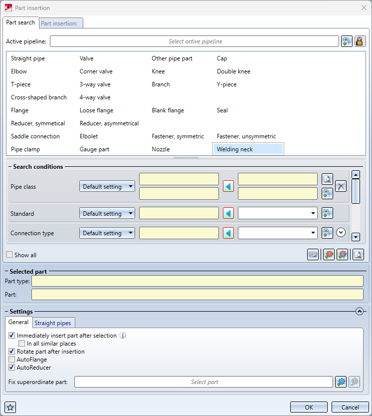
- Part insertion
The new Part insertion function offers for welding neck also the options AutoFlange and In all similar places.
- Pipe parts V26 and Part exchange
In the dialogues of the old Part insertion and Part exchange functions the welding neck can now also be found.
- AutoPlace parts on guidelines
AutoPlacing of parts on guidelines supports welding necks with the new option Welding necks on free ends.
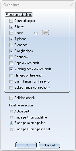
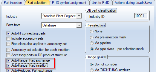
If this option is activated, then welding necks are placed on all free guideline ends, as for example with the option Flanges on free ends. If the option Counterflanges has been selected, welding necks that already exist individually will be counterplaced. If the AutoFlange... option is also activated on the Part selection tab of the Plant Engineering Settings dialogue window, welding necks are also automatically placed against the newly placed ones.
Loose flanges in the connection type attributes of straight pipes
As with welding necks, you can also define loose flanges in the connection type attributes for straight pipes. This is especially helpful for pipes with (one-sided) welding necks. This allows you to explicitly define the pipe ends where the loose flanges can be installed.
By eliminating the need to assign a standard in the connection type attribute, you also do not have to specify in the VAA file which loose flange you want to insert.
For this purpose the following flared pipe have been adjusted accordingly:
- EN10357_PIPE_BEADED_BOTH_PN10_FME4.VAA
- EN10357_PIPE_BEADED_BOTH_PN10_FME8.VAA
- EN10357_PIPE_BEADED_SINGLE_PN10_FME4.VAA
- EN10357_PIPE_BEADED_SINGLE_PN10_FME8.VAA
Align component connection tangentially, via context menu
The function Align connection tangentially was previously only available in the context menu of a component connection. These are sometimes difficult to identify, especially in drawings with a lot of parts..
To facilitate the use of this function, from HiCAD 2023 SP1 the function is also available in the context menu for pipe parts.
In this way, the selection is possible even if the component connection is hidden by other parts.
Isometry and Pipe spool drawing
Switch off symbol alignment
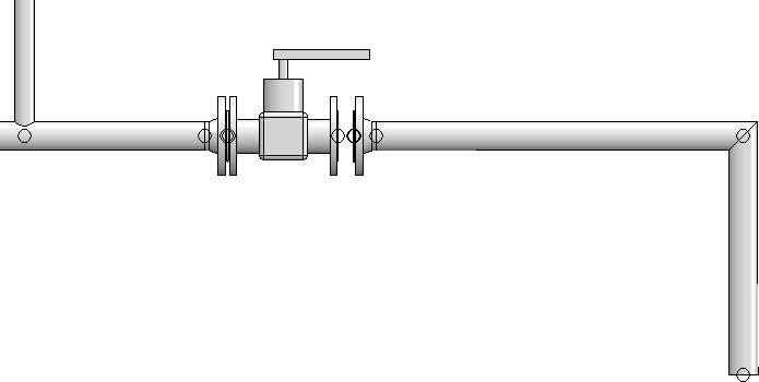
When creating an isometry or pipe spool drawing, HiCAD automatically aligns the symbolic representations of the parts.
Here is the example of the symbol of a valve installed between two flanges:
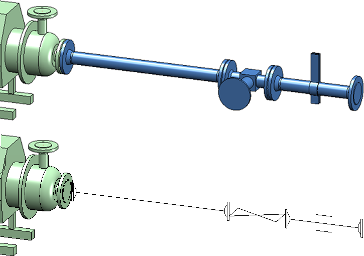
This usually looks like this in the isometry:
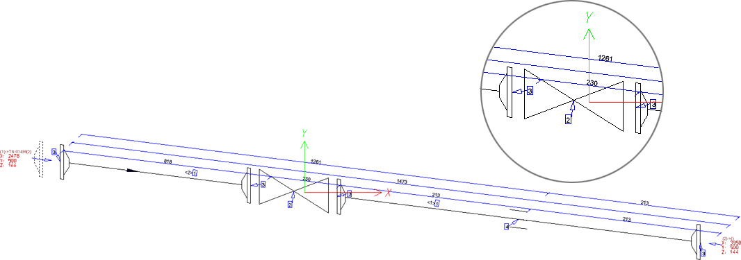
Until now, there was no way to bypass this automatism. As of HiCAD 2023 SP1, it is possible to disable this automatism in the Configuration Editor at Plant Engineering > Isometry and Pipe Spool Drawing > Align symbolic representations.
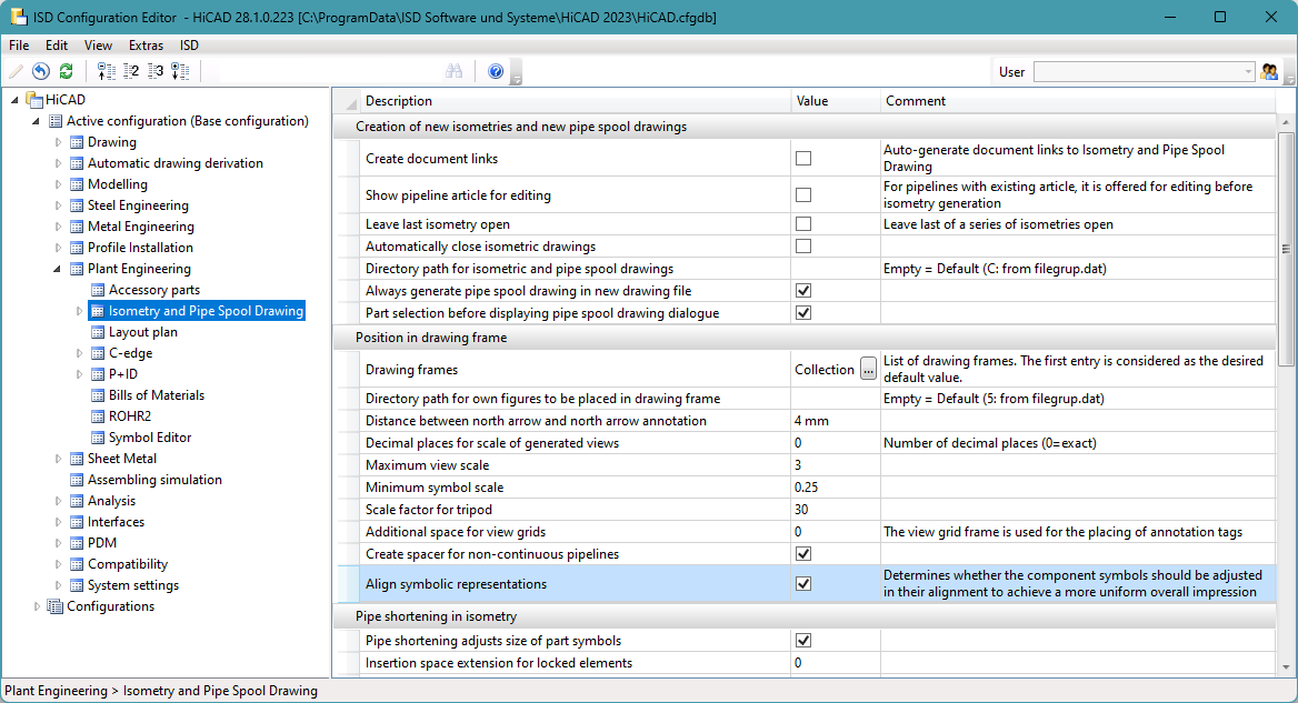
If the checkbox is deactivated, the result in the above example changes as follows:
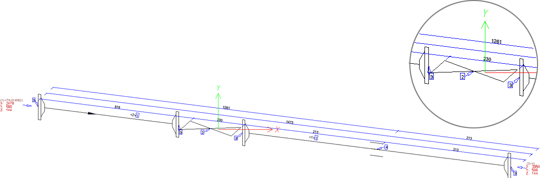
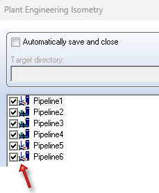
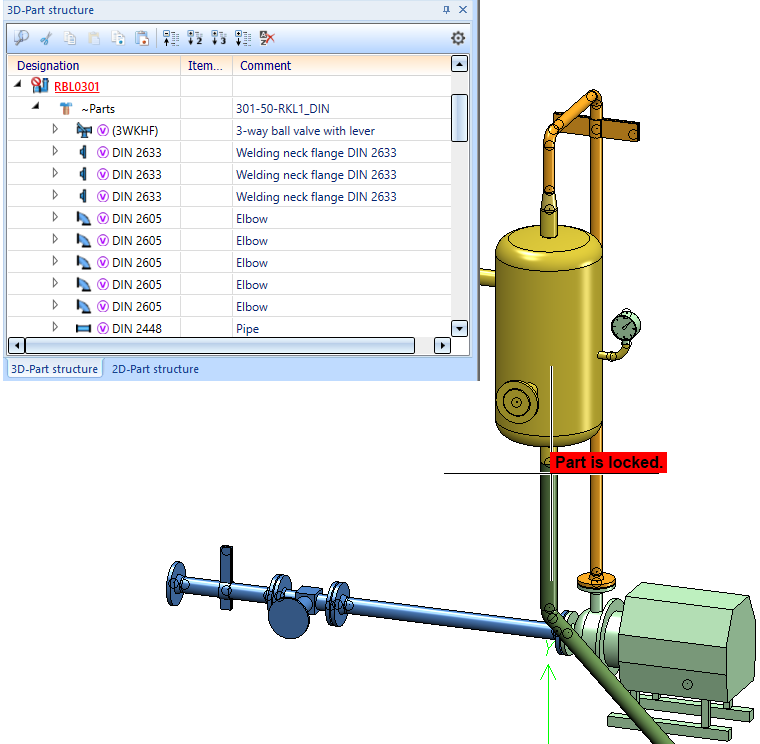
As a rule, you should leave the automatic symbol alignment switched on (ISD default setting).Exceptions can arise in individual cases, for example, if the symbol of a valve is to reflect the angle of its installation. In this case, you must manually adjust the symbol alignment in the layout plan. Please note that symbols are preferably rotated in groups in layout plan as well. So you may have to temporarily lock parts against editing, as shown in the following image for the two flanges in the ICN.
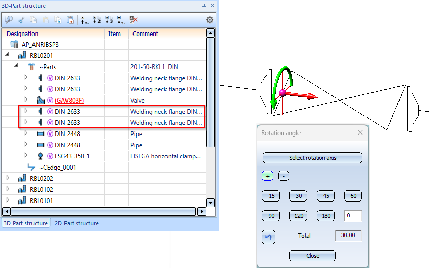
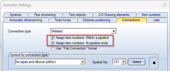
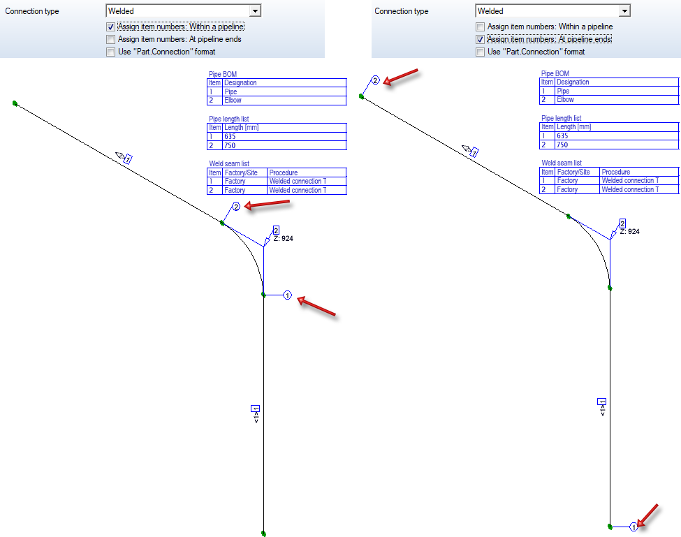
Connection item numbers at the end of/within pipelines
For connection item numbers it is now possible to determine whether they are to be assigned at pipeline ends or inside a pipeline. For this purpose the tab Connections in the isometry and pipe spool drawing settings has been extended..
Please note:
HiCAD tries to keep item numbers once they have been assigned. If you change one of these options, it is usually necessary to call the function Renew connection item numbers (Plant Engineering > Isometry / Pipe Spool Drawing > Spool) to get the desired result.
Update north arrow/crosshairs
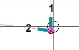
From SP1 onwards, it is possible to update the alignment of the north arrow and crosshairs on the sheet with the function Update all. The coordinate system of the active view is used for alignment. This is especially important in pipe spool drawing, where there is often more than one view.
The dialogues have been adapted accordingly:
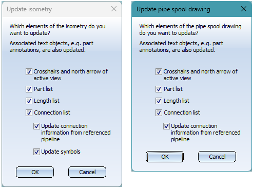
For the pipe spool drawing, crosshairs and north arrow have been added to the dialogue of the function Add/Remove pipe spool drawing elements:

In the following example the alignment has been changed manually in the lower view of the pipe plan. To reflect this in the crosshairs and the north arrow, the function Update is used.
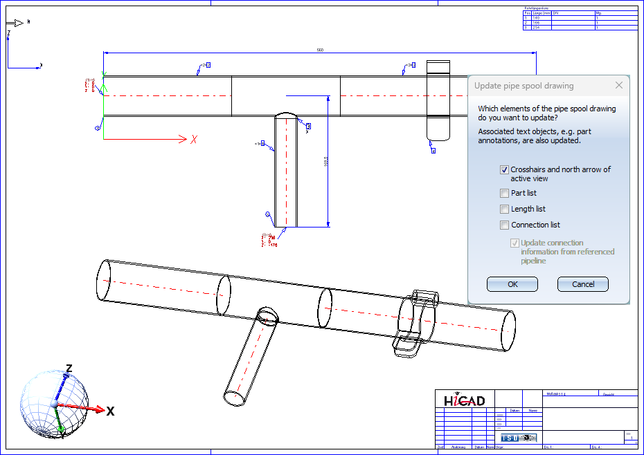
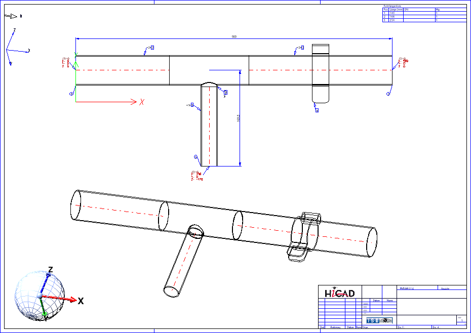
Since only one crosshairs and one north arrow are created, if there are several views you may have to adjust both figures on the sheet using the function 2-D Part > Transform > Move > Move part, free.
Major Release 2023 (V 2800)
New parts - Y-pipes
The parts inventory for Plant Engineering has been expanded by two variants for the part type Y-pipe:
- Y_PIPE_WELDED_60.VAA with an opening angle of 60° and
- Y_PIPE_WELDED_90.VAA with an opening angle of 90°.
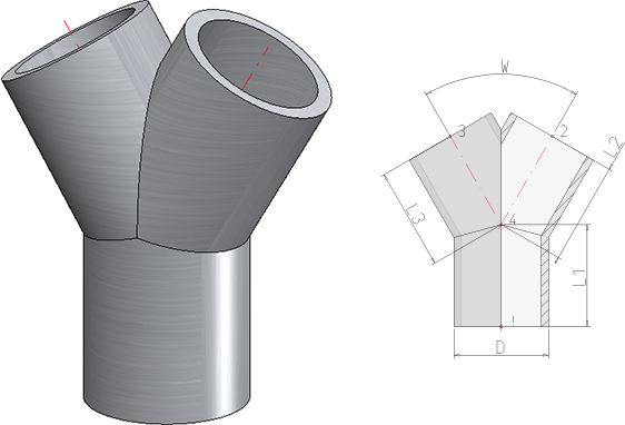
The geometry of these variants - in terms of outer diameter, wall thickness and the length of the "legs" - is based on the Y-piece YS.S from the company HECO®.
ROHR2 interface
Loose flanges
The program system ROHR2 does not allow overlapping pipe parts since version 33. Furthermore, parts cannot be transferred in such a way that they are only assigned to a connection point for representation. For this reason HiCAD 2023 does not transfer loose flanges to ROHR2 any more.
Naming of NTR files
When creating NTR files via the ROHR2 interface  , the part name of the pipeline was used as file name until now. From HiCAD 2023 onwards the name can be configured flexibly via HDB files.
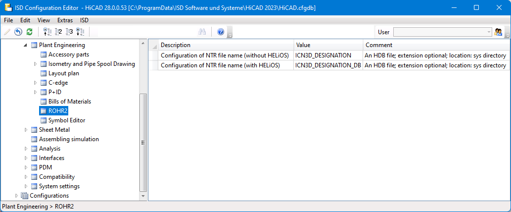
For this purpose the following parameters are available in the Configuration Editor at Plant Engineering > ROHR2.
- Configuration of NTR file name (without HELiOS) and
- Configuration of NTR file name (with HELiOS)
The files ICN3D_DESIGNATION and ICN3D_ DESIGNATION_DB are used as ISD default settings. These are the HDB files which are also used for the display of the column Designation of the ICN window 3D Part Structure. This means that the part number of the pipeline is used as the file name by default or - if this is not available - the part name.
If you want to use a different file name, you can adapt the files accordingly or use your own files. For more information, see the topic HDX and HDB Files.
When changing the ICN3D_DESIGNATION and ICN3D_DESIGNATION_DB files, please note that these changes also affect the ICN display!
Alternatively, you can create your own HDB files and set them in the Configuration Editor. The files must have the extension .HDB and be located in the HiCAD sys directory.
Example:
You want to use Designation 1 (Attribute $01) or Designation 2 (Attribute $02) of the pipeline as the names of the NTR files, but do not want to change the ICN display. Then you could create copies of the above files, e.g. ICN_NTR_PLANT and ICN_NTR_PLANT_DB, adapt them accordingly and then set them in the Configuration Editor:
|
ICN_NTR_PLANT.HDB |
ICN_NTR_PLANT_DB.HDB |
|---|---|
|
HDB # Configuration file for the output of any number of # HiCAD part attributes instead of the part name in the 3-D browser. # TEXT - Commentary ( will not be displayed ) # ATTR - Attribute to be displayed # TYP - STRING(default), DOUBLE # NKS - Decimal places # <H> - HiCAD part attribute # <E> - Features # _BEGIN_OR_ _END_OR_ - "ODER" link _BEGIN_OR_ <H>::TEXT=""::ATTR="$01"::TYP="WCHAR" <H>::TEXT=""::ATTR="$02"::TYP="WCHAR" <E>::TEXT="Teilename"::ATTR="NAME"::TYP="STRING" _END_OR_ |
HDB # Configuration file for the output of any number of # HiCAD part attributes instead of the part name in the 3-D browser. # TEXT - Commentary ( will not be displayed ) # ATTR - Attribute to be displayed # TYP - STRING(default), DOUBLE # NKS - Decimal places # <H> - HiCAD part attribute # <E> - Features # _BEGIN_OR_ _END_OR_ - "ODER" link _BEGIN_OR_ <T>::TEXT="Normbezeichnung"::ATTR="NORMBEZEICHNUNG" <T>::TEXT="Sachnummer"::ATTR="HEL_SACHNUMMER" <D>::TEXT="Dokumentnr."::ATTR="HEL_DOKUNUMMER" <H>::TEXT=""::ATTR="$01"::TYP="WCHAR" <H>::TEXT=""::ATTR="$02"::TYP="WCHAR" <E>::TEXT="Teilename"::ATTR="NAME"::TYP="STRING" _END_OR_ |
Load meta data
In the Part attributes dialogue window of a pipeline you can specify the
- Design pressure,
- Working pressure,
- Design temperature,
- Operating temperature and
- Density of medium
These attributes will be transferred during export via the pipeline interface.
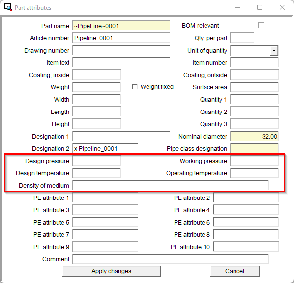
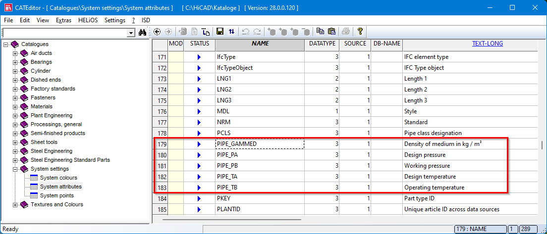
The catalogue System settings > System attributes has been extended accordingly for this purpose.
New Part insertion function
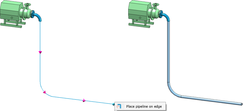
Straight pipes
When inserting straight pipes with the Pipe part function , from HiCAD 2023 only the option Place pipeline on edge is available in the context menu. This function has been extended and now places bent pipelines on bent guidelines:
Freely placeable parts
From HiCAD 2023 onwards, for parts that can be placed freely (e.g. T-pieces or branches), selecting an edge does not directly lead to the part being dropped. When you move the cursor near an edge, a preview is first displayed as follows:
Now you have two options:
- You click on the edge. Then a preview of the part is displayed as usual.
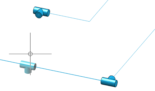
This part can now be flexibly aligned along the edges, for example at other connections. Only when the placement or connection point is selected does the insertion take place.
Alignment to other connections is also indicated graphically. If a guideline edge is selected and then another connection, the part will be aligned to that connection. This means that if the part can be rotated around the guideline edge so that the connection of the part and the selected connection are aligned, this rotation is suggested to you. A dashed line shows you that the connections are aligned with each other. 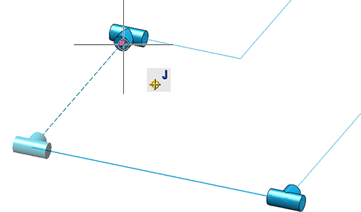
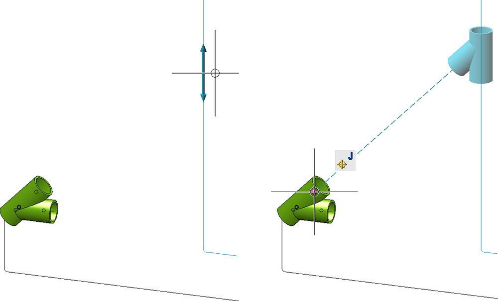
Otherwise, the next point on the guideline edge is used for placement.
- If the part is to be attached directly to another connection, select the desired connection or point without clicking the guideline edge first. The part will then be placed directly.
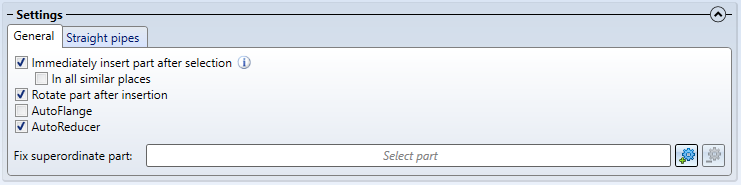
Immediate insertion in all similar places
If the checkbox Insertion in all suitable places is active in the dialogue on the General tab, then it is now also possible to specify whether the part is to be inserted automatically in all suitable places. A corresponding checkbox has been added to the dialogue.
This is possible for the following part types:
- Straight pipe,
- Elbow,
- T-piece,
- Knee,
- Branch and
- Flange.
First select an appropriate position, e.g. for an elbow.
The subsequently selected part is then installed at all suitable points (also applies to knees, T-piece and branches). For straight pipes, it is sufficient to select a point on the desired pipeline.
Flanges are a special case. Here there are two possible applications.
- The insertion position is the free end of a guideline.
Then the selected flange is placed at all free ends of the pipeline.
- The insertion position is the connecting point of a flange.
Then the same flange is installed as a counterflange at all points of the pipeline that have the same insertion situation.
Changed context menus
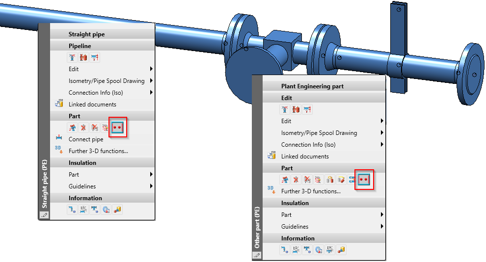
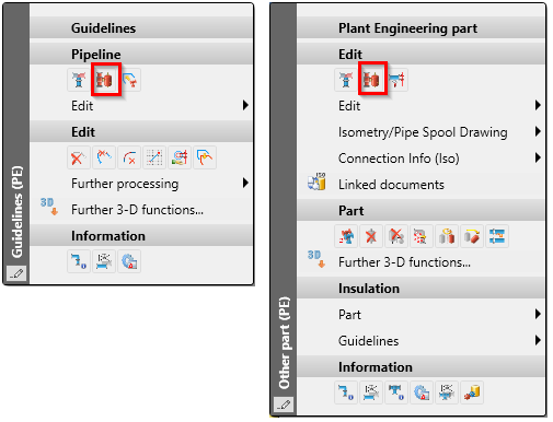
The function Pipe parts is now also available in the context menus for guidelines and Plant Engineering parts.
Down-grade Editor - Mitre cut straight pipes
The Down-grade Editor  has been extended by the option Mitre cut straight pipes. If this option is selected, straight, divisible pipes are mitred in order to place them in the down-grade.
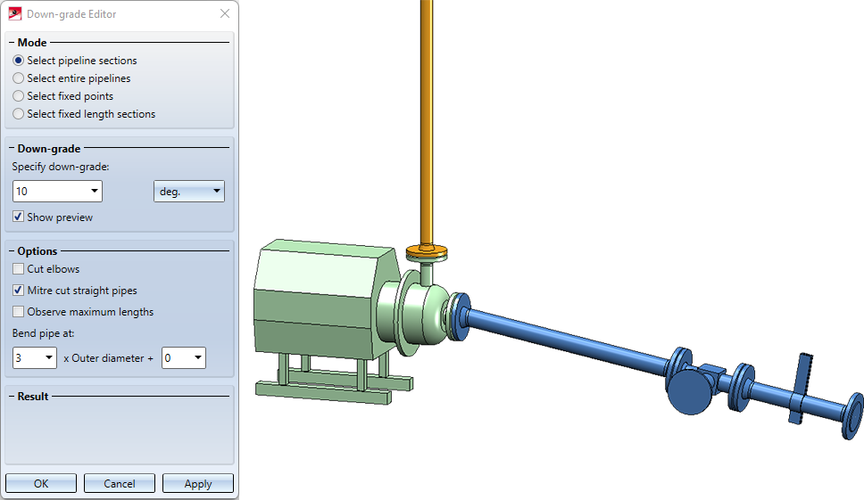
Note that the angle for the down-grade should not be too large in this case, as the mitre necessarily causes the pipe cross-section to deviate from the circular shape and thus no longer matches exactly the connection of the following pipe.
The angle for the mitre cut should not be too large, as otherwise pipe protrusions may result from the cut.
To place a pipe section in the down-grade, the Down-grade Editor now proceeds as follows:
- For pipes that already have a mitre (e.g. because it was set by the Edit arcs function), the mitre angle is changed.
- If the option Cut elbows is active, the angles of elbows are adjusted.
- If the option Mitre cut straight pipes is active, straight pipes are mitred.
- If none of the options apply, straight pipes are bent.
Copy, paste, mirror and clone pipelines
It is no longer absolutely necessary to copy pipelines from the pipeline planning via the corresponding function. The function takes care to keep the part name of the pipeline unique because the generation of isometry and pipe spool drawing require this.
- To copy and paste pipelines, you can also use the corresponding clipboard functions in the ICN:
- Copy to HiCAD clipboard
- Paste from HiCAD clipboard
When pasting from the clipboard, HiCAD takes care not to insert a pipeline below another pipeline.
-
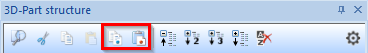
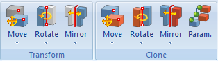
Pipelines can also be mirrored and cloned using the functions on the 3-D Standard Ribbon.
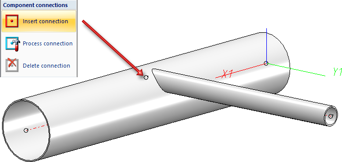
Eccentriccally inserted pipes
Up to now, straight pipes could only be inserted into other parts in such a way that the end point of the inserted pipe ends on the centre line of the other part. As of HiCAD 2023, this restriction no longer exists.
The prerequisite is that a connecting point is added to the part into which the tube is to be inserted, which can then act as the end point of the inserted tube. To add such a connecting point, use the functionInsert connection  (via Part Tools > Exchange > ...).
The insertion can then be carried out with the function Plant Engineering > New > PipePrt > Pipe parts v26 or Plant Engineering > Guideline Tools > AutoPlace parts on guidelines
 .
.
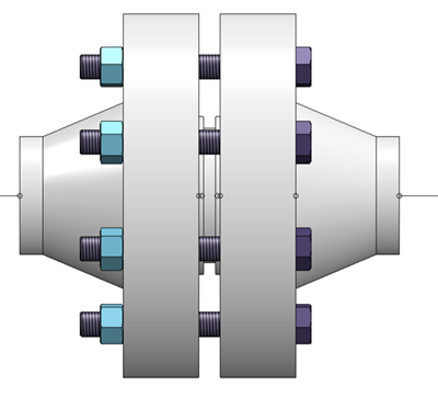
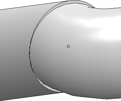
Common use cases are top-of-pipe or bottom-of-pipe insertion. The figure above shows the top-of-pipe insertion.
In both cases, the inserted pipe leads tangentially out of the thicker pipe, with the pipe placed as close to the edge of the thicker pipe as its wall thickness allows. In the following figure, this is indicated by the red line:
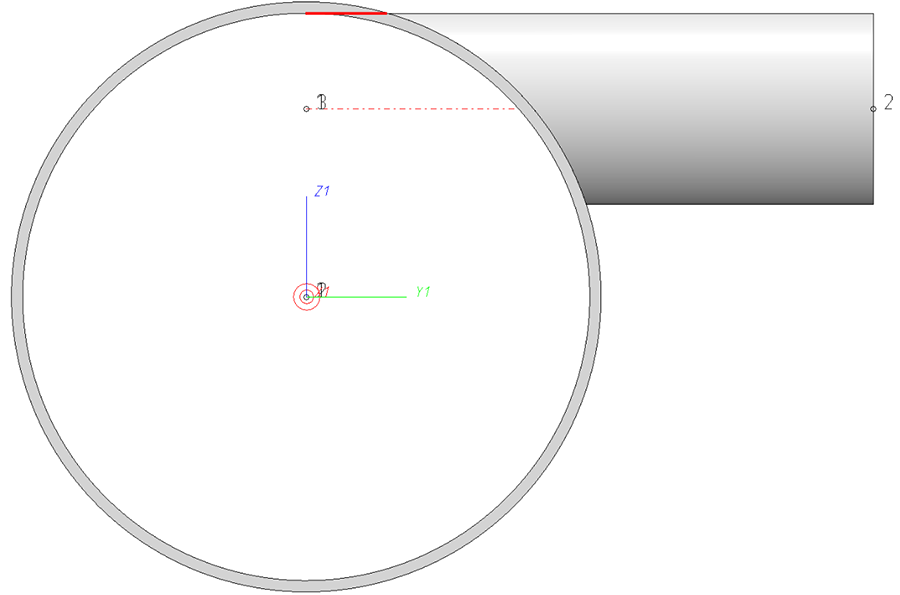
When setting the connection point freely, it is rather cumbersome to enter this point correctly manually. For this purpose, the outer diameter and wall thickness of the thicker pipe and the outer diameter of the pipe to be inserted must be calculated with each other. For this purpose, the Align connection tangentially  function is available in the context menu for connections:
Extensive information and an example can be found ion the topic Eccentrically Inserted Pipes.
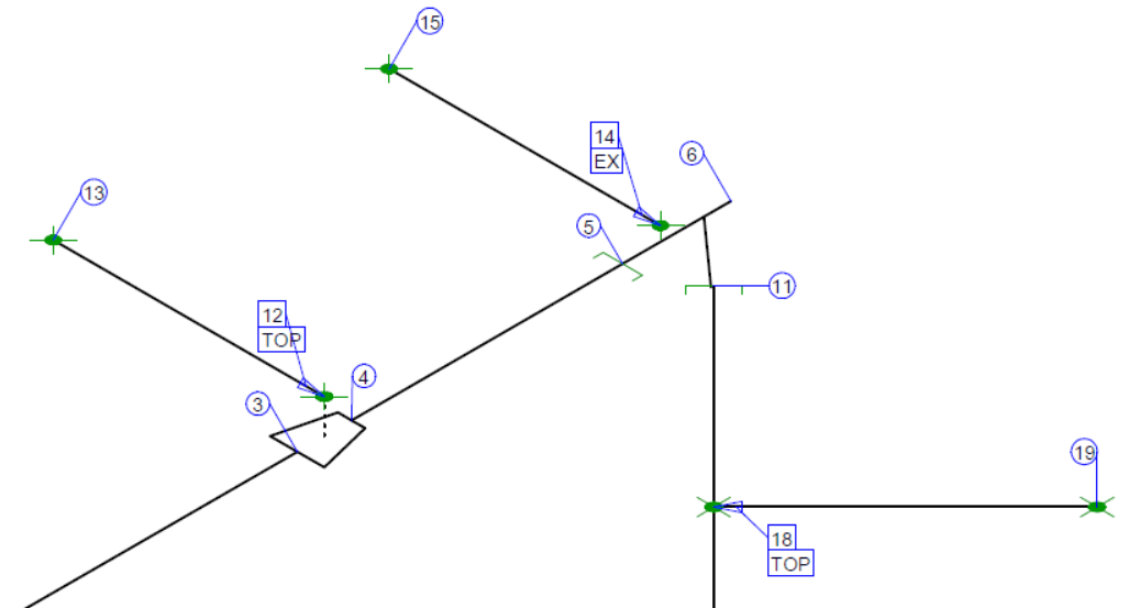
In addition, the display of connections in the isometry and in the pipe spool drawing has been extended. The additional texts TOP, BOP and EX are now displayed at the connection numbers of inserted eccentric pipes. This is the default setting for connections which are inserted:
- top-of-pipe (TOP),
- bottom-of-pipe (BOP) or
- otherwise eccentric (EX).
You can customize this representation by modifying the corresponding FTD files:
- ISD_inserted_top.ftd,
- ISD_inserted_bop.ftd and
- ISD_inserted_ex.ftd.
Especially if you want to have the concrete coordinates displayed at such points, these three text objects have to be adapted.
Delete multiple selection of parts
If several parts are selected in the drawing, then these parts can now also be deleted via the context menu of the multiple selection.
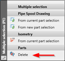
As described above, a distinction is made between parts that have been placed on a guideline and parts that have been placed in the drawing without a guideline.
Alternatively, you can also use the DEL key to delete parts in the ICN.
Lock parts
HiCAD offers the possibility to lock parts for other users; for example to protect it from accidental changing of parts. These parts are marked with a corresponding symbol  in the ICN.
For some Plant Engineering functions, a note is displayed in such cases to indicate the lock. The form of the message depends on the respective function.
- In some cases, the message is displayed directly during the selection of a pipeline, for example, in the case of the Move pipeline
 function.
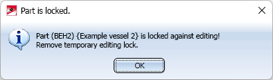
- In other cases, a corresponding message window is displayed, e.g.:
If a pipeline is locked, the following functions display a corresponding hint directly during the selection (some only if they are not called via context menu):
|
|
|
|
|
|
|
|
|
|
|
|
|
|
|
|
|
|
|
|


The message window appears when choosing the following functions:
|
|
|
|
|
|
|
|
|
|
|
|
|
|
|
|
|
Plant Engineering > Pipeline Tools > Change |


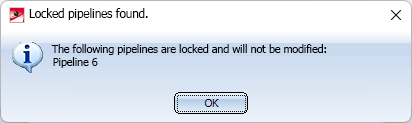
The function Plant Engineering > Pipeline Tools > Change > In all pipelines  handles locks by applying the desired change to all non-locked pipelines. The locked, i.e. not modified, pipelines are named in a message:
Bills of Materials (new ISD Report Manager)
Excel-BOM with pipe length list
For the new ISD Report Manager (from HiCAD 2023), an XML configuration file adapted for Plant Engineering is available with the name HiCAD_Anlagenbau.rm_settings . This configuration file allows the sensible creation of bills of materials (BOMs) of mixed model drawings.
The file is located in the HiCAD sys directory and facilitates in particular the use of a new BOM template for Excel export. This new template HiCAD_Anlagenbau.2800.0.xlsx can also be found in the sys directory of your installation (or as HiCAD_Anlagenbau.EN.2800.0.xlsx in the sub-folder bomtemplates).
Proceed as follows:
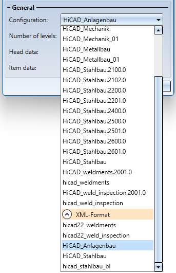
- To create a BOM, choose the function Drawing > Itemization/Detailing > BOM.
- In the dialogue window, select HiCAD_Anlagenbau for Configuration in the XML Format section.
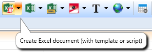
- When the BOM is displayed in the ISD Report Manager, select the Create Excel document (with template or script function there.
- After selecting a file name, Excel will open.
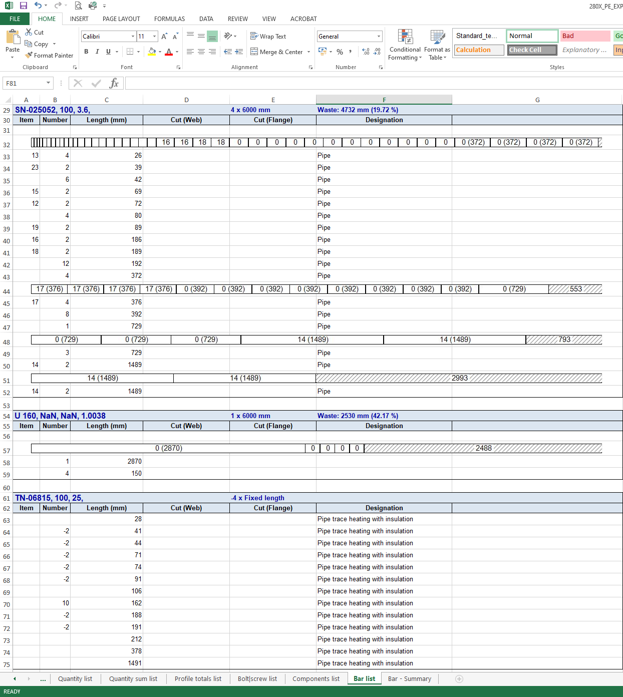
In the opened file you will now find the following BOMs (as Excel tables):
|
Table |
Content |
|---|---|
|
Structure list |
Displays all individual parts and assemblies of a product on the basis of the HiCAD part structure, i.e. a summary of all production stages with logical relationships |
|
Quantity list |
Displays the quantity per item, i.e. without further summary |
|
Quantity sum list |
Shows the quantity per article, where length, area and weight are summed up |
|
Profile totals list |
A grouped layout of the quantity list for articles with length |
|
Components list |
A grouped layout of the quantity list without even pipes or articles without length |
|
Bar list |
Similar to the profile totals list, but grouped by delivery length with remainder |
|
Bar - Summary |
Basically the table headers from the bar list, so a summary of the bar list |
Example:
BOM-creation with Plant Engineering functions
Adapted configuration files for the new ISD Report Manager are also available for the Plant Engineering functions at Plant Engineering > Evaluation:
- Entire drawing: ANLAGENBAU_SZN.RMS_settings
- Active pipeline: ANLAGENBAU_RL.RMS_settings
- Total length list: ANLAGENBAU_GESLEN.RMS_settings
These are preset in the Plant Engineering Settings, on the Bills of Materials tab.
Furthermore, as of HiCAD 2023, only two HDB files control which attributes are transmitted to the ISD Report Manager:
- rm_anl_exportszn.HDB (für Konstruktionen) und
- rm_anl_exportpart.HDB (für Teile)
These contain HiCAD part attributes only. If you need additional attributes of the HELiOS PDM system, the prepared files
- rm_anl_exportszn_db.HDB und
- rm_anl_exportpart_db.HDB
serve as templates. You will find the files in the HiCAD sys directory. In the simplest case, it is sufficient to rename them accordingly:
- rm_anl_exportszn_db.HDB
 rm_anl_exportszn.HDB
 - rm_anl_exportpart_db.HDB rm_anl_exportpart.HDB
|
Prior to HiCAD 2023, when creating the total length list using the Total length list for straight pipes As of HiCAD 2023, when creating the total length list with an rm_settings configuration file of the ISD Report Manager, the total length will be assigned to the attribute Total length (§22). Thus, the total length is also available in the ISD Report Manager as a length with a suitable unit.. |
 function, the total length was assigned to the
Rotate flange connections
When installing parts with sub-part flanges, e.g. valves, if you rotate the part after insertion, these flanges will now be rotated as well. The same applies if the AutoFlange option is activated.

This functionality is only offered by the new Part insertion function, via the old one (V26) only the valve or similar is rotated as before. If the parts are to be rotated together, either the new Part insertion function is to be used or one places the parts first without rotation and then uses the function Rotate part.
HiCAD - HELiOS Head ID
As of HiCAD 2023, it is no longer possible to specify the Head IDs of articles and documents in HELiOS. This ID was previously used by the catalogue editor and the DBPlantDataImport/PartDataAutoSync tools to find articles again.
Now, unique IDs are assigned by the variant editor itself and transferred to HELiOS during matching. These IDs are directly visible in HELiOS, as they are not a regular article attribute.
The new IDs are only directly visible in a few places in HiCAD:
- When matching with the catalogue via the tool VarToCat, an additional table column PLANTID is inserted.
- In P+ID, the new ID becomes visible in the attribute Database article ID when assigning article data.
- After a part has been installed, the PLANTID is also found in its part attributes.
