Straight pipes can be inserted into other parts of the type
- Straight pipe,
- Elbow,
- Knee,
- T-piece,
- Branch and
- Reducer, concentric.
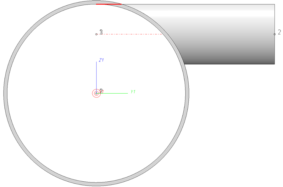
The end point of the straight pipe does not necessarily have to end on the centre line of the other part, but can be any point.
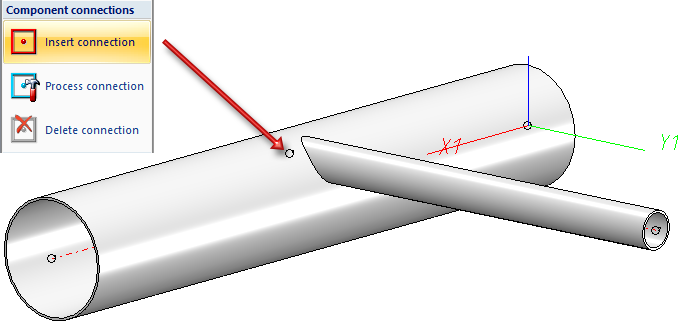
The prerequisite, however, is that a connecting point is added to the part into which the pipe is to be inserted, which can then act as the end point of the inserted pipe.
To add such a connecting point, use the function Insert connection  (via Part Tools > Exchange
  > ....).
The insertion can then be carried out with the function
- Plant Engineering > New > PipePrt > Pipe parts
 or
or - Plant Engineering > Guideline Tools > AutoPlace parts on guidelines

Common use cases are top-of-pipe or bottom-of-pipe insertion. The figure above shows the top-of-pipe insertion.
In both cases, the inserted pipe leads tangentially out of the thicker pipe.
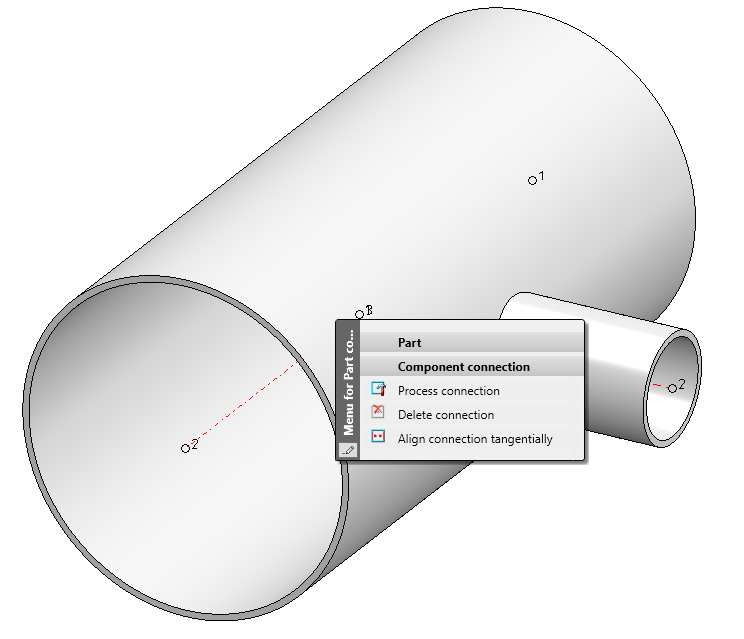
When setting the connection point freely, it is rather cumbersome to enter this point correctly manually. For this purpose, the outer diameter and wall thickness of the thicker pipe and the outer diameter of the pipe to be inserted must be calculated with each other. For this purpose, the Align connection tangentially function is available in the context menu for connections:
When you call this function, HiCAD asks you to enter the distance to the outer wall:
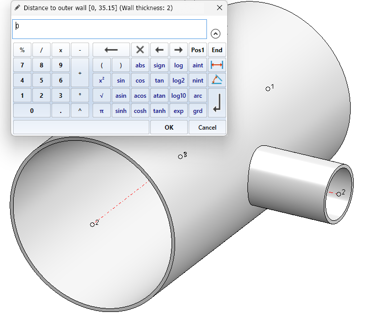
Note the interval specification in the caption of the dialogue. This comprises the sensible input range (in the example: [0. 33.15]). In the user guidance text this is repeated again. In addition, the wall thickness of the larger pipe is displayed in the caption of the input window.
If you want to align the pipe top-of-pipe or bottom-of-pipe, you can accept the suggested value 0. The maximum value of the input range (here: 33.15) would align the pipe centrally.
If the pipe is not centrally aligned at the beginning, the point in the middle of the pipe is also offered for selection when 0 is entered, so that you do not need to type in the maximum value in this case.
So if you accept 0 in this example, the two possible target points appear, from which you select one:
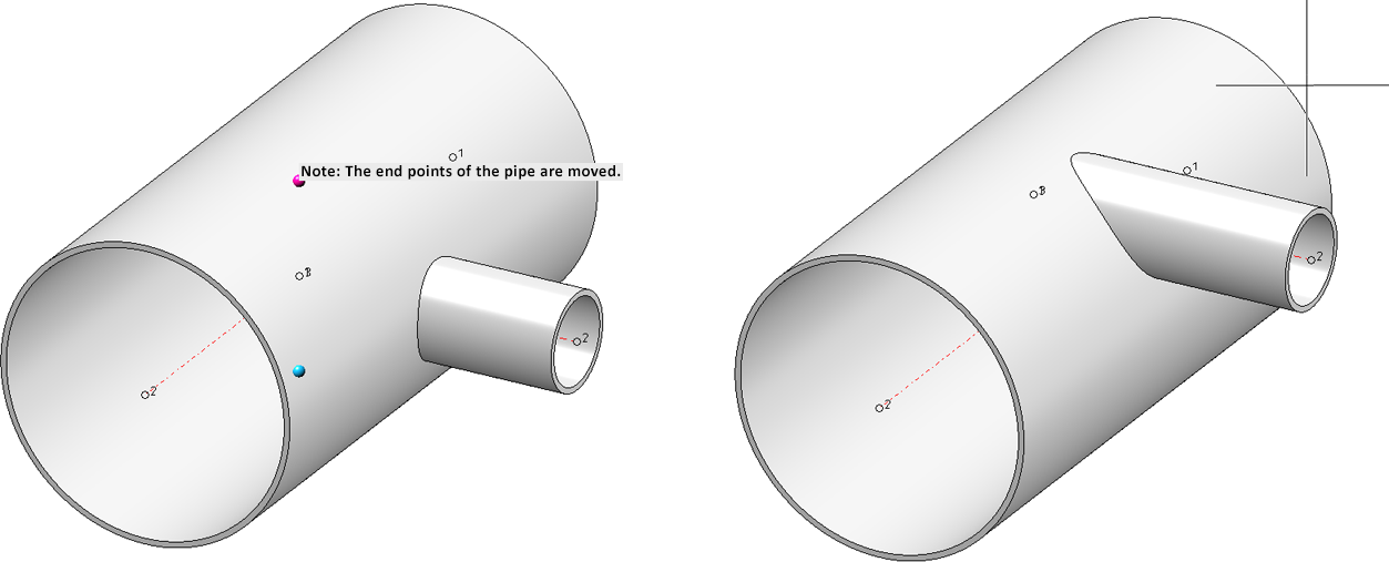
On the right you see the result after selecting the upper point. Note the information text at the target point. HiCAD points out that when you change the position of the inserted pipe, end points of the pipeline are moved. This is obvious in our example, but not necessarily so for longer pipes or part sequences. Internally, the progression change is used to adjust the position of the inserted pipe, and preferably pipe end points are not moved.
Another message you will see from time to time is an indication of a possibly inaccurate target position, as with the following reducer:
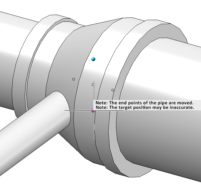
Outside diameter and wall thickness are calculated from the attributes that define these values for the connecting points. In between, interpolation is performed. The calculated values therefore only match the component geometry exactly for the simplest geometries, hence the note.
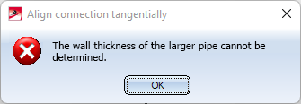
Since the attributes of the component are used for the calculation of the target points, the tangential alignment fails if these attributes are missing. Then, for example, the following message appears:
![]() Please note:
Please note:
- To avoid unaesthetic protrusions on the inserted tubes, the function ensures a minimum constructive distance of 0.1mm.
- To change the angle of inserted pipes, use the Down-grade Editor or the Route change function.
- See also the notes on inserted pipes when creating isometry and pipe spool drawing.


Pipe Parts(PE) • Part Selection - Catalogue or Database (PE) • General Information on Pipe Parts (PE) • Settings: Straight Pipes (PE)