Reference Coordinate System
Set reference CS for isometries
Plant Engineering > Isometry / Pipe Spool Drawing > Set reference CS for isometry 
Normally the world coordinate system of the layout plan is used as the reference coordinate system for determining coordinates in the isometries and pipe spool drawings. However, you can give pipelines a reference coordinate system that is taken into account when generating isometries and pipe spool drawings, e.g. when displaying coordinates in annotation tags.
The prerequisite is that a local coordinate system exists in the layout plan. For this purpose you can use, for example, the function Plant Engineering > Settings > Settings  > Set on connection
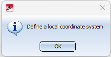
  . If no local coordinate system is defined, a corresponding message appears:
If a local coordinate system exists, you are prompted to select a pipeline when you start the Ref... function. you will be asked to select a pipeline.
As soon as the graphic cursor is moved over a pipeline, it is displayed directly at the cursor whether the pipeline already has a reference coordinate system.
One of the three following messages can be displayed:
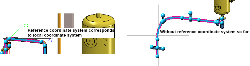
- Without reference coordinate system so far
By clicking on the pipeline the local coordinate system is taken over as the reference coordinate system of the pipeline. - Reference coordinate system corresponds to local coordinate system
- Reference coordinate system deviates from local coordinate system
The local coordinate system has been changed subsequently.
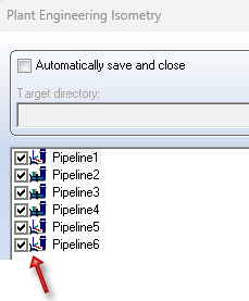
In the dialogue of the isometry as well as the pipe spool drawing generation it is marked by the  symbol whether a pipeline has a reference coordinate system.
Clicking on opens a sub-menu with the function Delete reference CS for isometry  .
.
 This function can also be applied to pipe spool drawings.

Delete reference CS for isometries
Plant Engineering > Isometry / Pipe Spool Drawing > Ref. > Delete reference CS for isometry
If previously the local coordinate system of the layout plan was declared the reference coordinate system of a pipeline, then with this function the world coordinate system of the layout plan again becomes the reference coordinate system of the pipeline in the isometry or pipe spool drawing.
As soon as the graphic cursor is moved over a pipeline, you are informed directly at the cursor whether the pipeline already has a reference coordinate system. The messages are the same as when setting a reference coordinate system.
This function can also be applied to pipe spool drawings.

Isometry and Pipe Spool Drawing (PE/Iso) • Isometry and Pipe Spool Drawing Functions for the Layout Plan (PE) • Plant Engineering Functions • Local Coordinate System (PE)