Create/Update Drawing - Automatic
Management + BIM > Workshop > Drawing 
- Auto-create workshop and detail drawings and
- Update workshop, detail, mounting and customer drawings after changing the model drawing.
In contrast to the Create/Update - Manual  function the settings for drawing derivation (e.g. for Drawing sheets, View groups, Views etc.) will not be specified in the dialogue window here, but will be loaded from the corresponding pre-settings files when you create the workshop/detail drawings. Therefore, the Drawing derivation dialogue will not be displayed here, which speeds up the drawing creation process.
 Mounting drawings and customer drawings cannot be created with this function, but only updated (if there are any drawings). However, the updating will only work if the drawings have the status In progress. In this context, please also read the information given in the chapters Customer Drawings, Mounting Drawings and Change Released Drawings.
When you call the function it will be checked
- for which parts of the model drawing no workshop or detail drawing exists yet,
- which drawings (including mounting and customer drawings) are no longer up to date, and
- whether parts for which drawings existed have been deleted in the model drawing.
The result will be shown in a selection mask. Here, all articles with the links
- Drawing not up to date,
- Mounting drw. not up to date,
- Customer drw. not up to date and
- Deleted
will be listed.
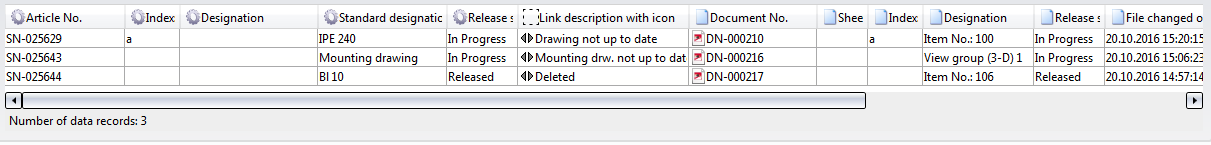
Select the parts for which a drawing needs be created (or updated), and click OK. The selected parts will be highlighted in the model drawing and the following message appears:
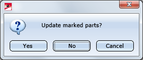
When you click on Yes, the drawings for the highlighted parts will be updated or deleted.
Please note that drawings belonging to deleted parts will only be removed after project clean-up.
See also Delete Drawing.
Then, all parts with the "Without drawing" link (i.e. all parts for which no production drawing exists yet) will be listed.
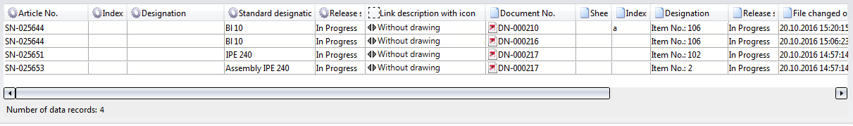
Now, select the parts for which you want to create production drawings and confirm with OK. The selected parts will be highlighted in the drawing and the following message appears:
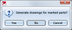
Click Yes to create the drawings for the selected parts. Inputs in the Drawing derivation window are not required here, since the settings for drawing derivation will be loaded from the appropriate presetting files here.
The workshop drawing will be created immediately as a Sheet a new model drawing. Sheet views can be opened in the Views tab of the ICN.
By default, the following template files are supplied with HiCAD(in the SYS directory):
|
File |
Settings for | |
|---|---|---|
|
BIM_WSD_Default_Assembly.DAT |
Assemblies |
|
|
BIM_WSD_Default_IndividualPart.DAT |
Individual parts
|
|
|
BIM_WSD_Default_Bolted_Assembly.DAT |
Bolted assemblies (Site) |
|
|
BIM_WSD_Default_Welded_Assembly.DAT |
Welded assemblies (Workshop) |
|

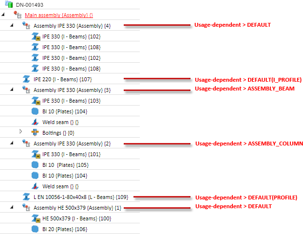
In the supplied settings files, the drawing parameters will be specified via configuration, i.e. the settings in the Configuration Editor at Automatic drawing derivation > Production drawing > Usage-dependent will be used. This means:
- For general assemblies to which no usage has been assigned the settings at ...Usage-dependent > DEFAULT will be used.
- For assemblies to which a usage has been assigned, the settings for the corresponding usage at ...Usage-dependent will be used, e.g. for beam (girder) assemblies the settings at ... >Usage-dependent > ASSEMBLY_BEAM.
- For individual parts of the type Flat steels, Hollow profiles, I-beams or steel pipes the corresponding settings at ...Usage-dependent will be used,e.g. for I-beams the settings at ...Usage-dependent > DEFAULT(I_PROFILE). For other beams and profiles, the settings at ... >Usage-dependent > DEFAULT(PROFILE) will be used.
- For individual parts to which no part type has been assigned, the settings at ... >Usage-dependent > DEFAULT will be used.
- For bolted and welded assemblies ("Site" and "Workshop" assemblies) the settings at ... >Usage-dependent > DEFAULT used.
Example:
If an external production document, e.g. a PDF file, has been opened in HELiOS, a drawing that is linked to it cannot be updated in HiCAD.
 Please note:
- When you create or update production drawings, the settings in the Configuration Editor at PDM > Management + BIM > External production drawings will be considered.
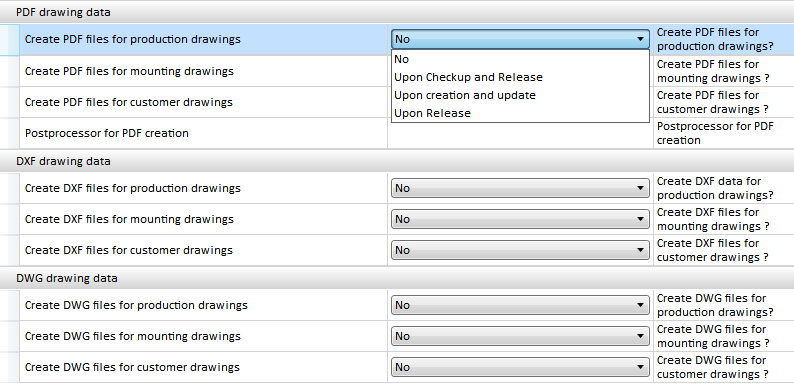
If the setting Upon Checkup and Release has been chosen for the Create ... files for production drawings parameters beneath External drawing data, the corresponding DXF, DWG or PDF files will be created for the production drawings. Please note that a Postprocessor needs to be specified for PDF files.
- Derived drawings which have been automatically generated with the Management + BIM functions are locked against manual modifications. When you try to change any parts in the drawing, the following message will be displayed: Automatically detailed parts cannot be processed in automatically created external production drawings.
- The parts of the automatically created drawings are (unilaterally) referenced in the direction of the original drawing and marked in the ICN with the
 symbol. The referencing is unilateral, i.e. in case of changes to the model, the workshop drawing can automatically be updated.
- Ensure that the required HiCAD catalogues (Fasteners etc.) are also available in HELiOS. If this is not the case, you need to transfer them, via the Catalogue Editor, to HELiOS.(for further information please see the Online Help of the Catalogue Editor).
- The settings in the Configuration Editor at PDM > Management + BIM will be considered for drawing derivations.
- When adding view groups in Sheets with already existing views of a derived drawing, you have nor the option to deactivate the rearranging of the existing views. This setting can be speicified in the Configuration Editor at ... > Automatic drawing derivation > Production drawing > Rearranging existing views when adding view groups - Do not rearrange. The default setting is Query.
- For external PDM-managed drawings you can now specify whether missing sectional views are to be created in case of an updating of derived drawings. In the Configuration Editor, select ... > PDM > Steel Engineering Drawing Management and set the parameter AutoSync sectional view when updating PDM-managed drawings as required. The default setting is Adjust.
It is also possible to switch off the automatic rearranging of views. In the Configuration Editor. Select ... > PDM > Management+BIM and set the parameter Rearrange views when updating PDM-managed drawings as required. The default setting is Rearrange.
- Do not use this function for an automatic updating of production documents! Instead, use the functions in the Production function group for this.
- If an automatically generated article master is not used in a super-ordinate article master, and a part with no links exists, the product structure of the part will be deleted before a general clean-up takes place.
- If released customer drawings with old parts exist for the current model drawing, the following message will be displayed:
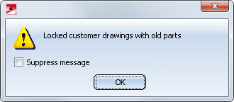
This will, for instance, be the case if, after a release of customer drawings, changes are applied to parts in the 3-D model that belong to one of these customer drawings.
After clicking OK, a list of the old parts will be displayed.
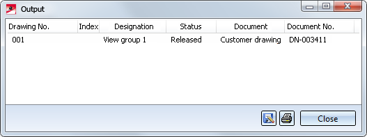
To be able to update these customer drawings, you first need to call the Revision index  function and choose the corresponding customer drawing to remove the Release again. Then, choose the Drawing function to update the customer drawing. The status of the drawing will then be reset to In progress. With the functions in the Customer... pull-down menu you can then request an approval and release the drawing again.
Use the Locked old drawings  function to check whether locked customer drawings with old parts exist.
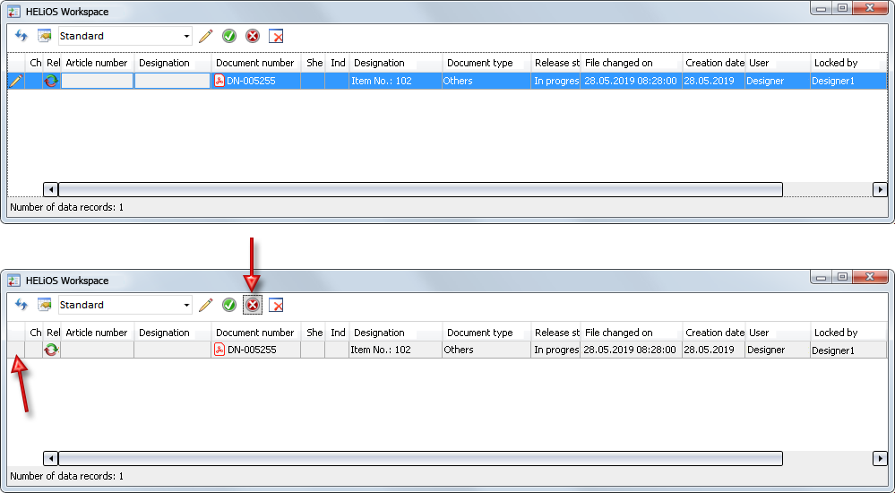
- If an external production document, e.g. a PDF file, has been opened in HELiOS, a drawing that is linked to it cannot be updated in HiCAD. In such as case HiCAD will issue the message shown below and list the documents in another window:
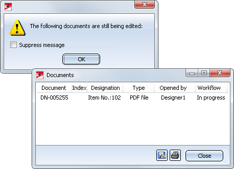
In this situation you have the option to end the editing by choosing (Extras > Show workspace  ) and clicking on the
  symbol in the HELiOS workspace dialogue window. When you then perform an update, the opened external document, too, will be updated in the background. When you open this document again, all changes will then be visible.

Creating your own settings files
Besides the option to use the predefined settings files supplied with HiCAD, you can also create, depending on the respective usage/part type, your own settings files.
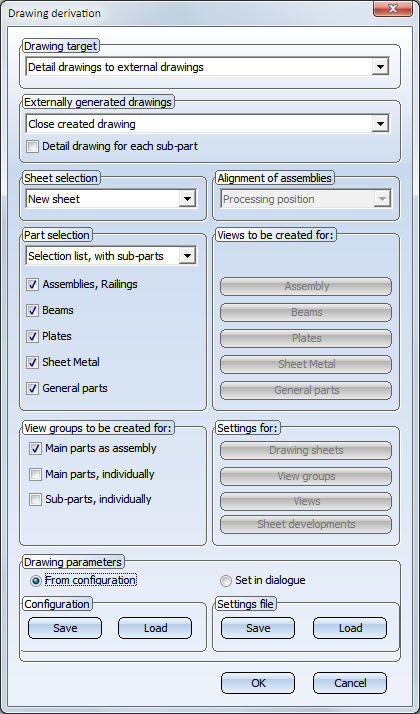
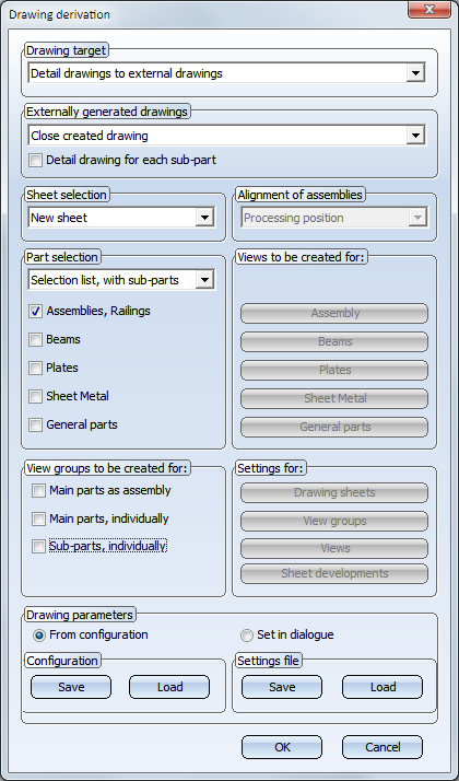
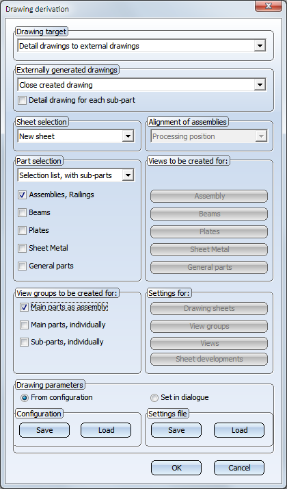
To create or modify such files, select Drawing > Itemisation/Detailing > Derive  . Specify the desired settings in the dialogue. To Save the settings in a settings file, or to Load an existing file, use the buttons beneath Settings file.
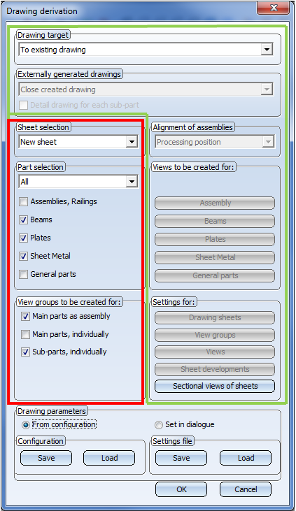
The area in the red frame is controlled by the corresponding .DAT file, the area in the green frame by the settings in the Configuration Editor.
The presetting files must be given the following names:
- BIM_WSD_UsageText.DAT or
- BIM_WSD_UsageKey.DAT
with UsageText standing for the designation in the tables of the Factory Standards catalogue Usage, and UsageKey standing for the CONFIGKEY.
|
Catalogue |
Table |
UsageKey = CONFIGKEY |
UsageText = Designation |
|---|---|---|---|
|
General |
Column |
COLUMN |
Columns |
|
Girder |
BEAM |
Girder |
|
|
Metal Engineering - Elements
|
Contact profile |
MC_STRIP |
Contact profile |
|
Cover bar |
MC_COVERBAR |
Cover bar |
|
|
Seal |
MC_GASKET |
Seal |
|
|
Inserted profile |
MC_INSERTIONBAR |
Inserted profile |
|
|
Isolator |
MC_ISOLATOR |
Isolator |
|
|
Support profile |
MC_PROFILE |
Support profile |
|
|
Connector |
MC_CONNECTOR |
Connector |
|
|
Metal Engineering - Groups |
Fixing bracket |
BEFESTIGUNGSKONSOLE |
Fixing bracket |
|
Inserts |
MC_LOGIKALOBJECT |
Insert |
|
|
Top or base point |
MC_BRACKET |
Facade base point Facade top point |
|
|
Mullion |
MC_MULLION |
Mullion |
|
|
Mullion connection |
PFOSTENSTOSS |
Mullion connection |
|
|
Transom |
MC_BAR |
Transom |
|
|
Steel Engineering - Assemblies
|
Stabilizing pipe |
STABILIZING_PIPE |
Stabilizing pipe |
|
Cross-bracing |
CROSS_BRACING |
Cross-bracing |
|
|
Steel frame |
FRAME |
Frame |
|
|
Welded beam/profile |
WELDED_I_SECTION |
Welded I-beam |
|
|
WELDED_BOX_SECTION |
Welded box profile |
||
|
WELDED_CROSS_SECTION |
Welded cross-profile |
||
|
WELDED_SEMICROSS_SECTION |
Welded cross-profile, half |
||
|
Column assembly |
ASSEMBLY_COLUMN |
Column assembly |
|
|
Girder (beam) assembly |
ASSEMBLY_BEAM |
Girder (beam) assembly |
|
|
Steel Engineering |
Plate types |
FILLER-PLATE |
Filler plate |
|
BASE-PLATE |
Base plate |
||
|
TOP-PLATE |
Top plate |
||
|
STIFFENER |
Stiffener |
||
|
REINFORCEMENT-PLATE |
Reinforcement plate |
||
|
Railing |
SKIRTING |
Skirting board |
|
|
SKIRTINGPROFILE |
Skirting board profile |
||
|
WEBMEMBER |
Rod |
||
|
FILLING |
Infill |
||
|
RAILING |
Railing |
||
|
RAILINGSEGMENT |
Railing segment |
||
|
STRINGER |
Boom |
||
|
HANDRAIL |
Handrail |
||
|
RAILINGPROFILE |
Handrail profile |
||
|
KNEERAIL |
Kneerail |
||
|
POST |
Post |
||
|
POSTPROFILE |
Post profile |
||
|
GLASSPANE |
Glass |
|
Alternatively, you can also use the part type: BIM_WSD_Teileart.DAT. This file must be created, for instance, if you
|
For example, if you require particular settings for I-beams, you need to create a BIM_WSD_I - Profile.DAT file.
| Part type | Catalogue | Part type | Catalogue |
|---|---|---|---|
|
A1 Girder |
Factory standards > Factory beams > Frankstahl |
Glass panes |
Factory standards |
|
A3 Steel bar |
Factory standards > Factory beams > Frankstahl |
Hollow profiles |
Factory standards > Factory beams > Frankstahl > A4 Shaped tubes, Hollow profiles, Profiles |
|
General |
Factory standards > Usage > Civil Engineering |
Wood |
Semi-finished products |
|
B1 Commercial tubes, seamless |
Factory standards > Factory beams > Frankstahl |
IN-HOUSE_PROFILES |
Factory standards > Factory beams |
|
B2 Commercial tubes, welded |
Factory standards > Factory beams > Frankstahl |
Cold-rolled sections |
Semi-finished products |
|
B4 Mechanical stress-resistant steel pipes |
Factory standards > Factory beams > Frankstahl |
Crane rails |
Semi-finished products > Beams+Profiles |
|
B5 Precision steel pipes |
Factory standards > Factory beams > Frankstahl |
L - beams |
Semi-finished products > Beams+Profiles |
|
B6 Hydraulic components |
Factory standards > Factory beams > Frankstahl |
Profiles |
Semi-finished products Factory standards > Factory beams > Frankstahl > A4 Shaped tubes, Hollow profiles, Profiles |
|
Reinforced steel |
Semi-finished products > Beams+Profiles |
Round steels |
Semi-finished products > Beams+Profiles |
|
Plates |
Semi-finished products |
Hexagonal steels |
Semi-finished products > Beams+Profiles |
|
C-beams |
Semi-finished products > Cold-rolled sections |
Steel pipes |
Semi-finished products > Beams+Profiles |
|
C1 Pipes and Profiles |
Factory standards > Factory beams > Frankstahl |
T - beams |
Semi-finished products > Beams+Profiles |
|
C3 Stainless steel bars |
Factory standards > Factory beams > Frankstahl |
U - beams |
Semi-finished products > Beams+Profiles Semi-finished products > Cold-rolled sections |
|
Flat steel |
Semi-finished products > Beams+Profiles |
Square steel |
Semi-finished products > Beams+Profiles |
|
FLUTZ profile |
Factory standards > Factory beams |
Voest profiles |
Factory standards > Factory beams |
|
Formed tubes |
Factory standards > Factory beams > Frankstahl > A4 Shaped tubes, Hollow profiles, Profiles |
Z - beams |
Semi-finished products > Beams+Profiles |
|
Gratings |
Semi-finished products |
|
|
During automatic drawing creation HiCAD will check for each usage / part type whether pre-settings already exist, namely, in the following order:
- If a settings file BIM_WSD_UsageText.DAT exists for a usage, this file will be used, and Step 1 will be repeated for the next usage. If such a file does not exist, the search will be continued with Step 2.
- If no settings file BIM_WSD_UsageText.DAT exists,HiCAD will search for a BIM_WSD_UsageKey.DAT file. If such a file exists it will be used, and this step will be repeated for the next usage. If such a file does not exist, the search will be continued with Step 3.
- If neither the file BIM_WSD_UsageText.DAT nor the file BIM_WSD_UsageKey.DAT exists, the default files will be used for assemblies. For individual parts, HiCAD will search for files with the name BIM_WSD_PartType.DAT. If such files exist, these will be used for the corresponding part types. For all other part types, the settings from the file BIM_WSD_Default_IndividualPart.DAT will be used.
Example:
Let us assume that, besides the default settings flies, the following files exist:
- BIM_WSD_Column assembly.DAT and
- BIM_WSD_I - beams.DAT.
In this case, the settings from the file BIM_WSD_Column assembly.DAT will be used for all assemblies with the usage Column assembly; for all other assemblies, the settings from the default files will be used, i.e. the settings from the file BIM_WSD_Default_Assembly.DAT for general assemblies, and the settings from the files BIM_WSD_Default_Bolted_Assembly.DAT or BIM_WSD_Default_Welded_Assembly.DAT, respectively, for bolted assemblies or welded assemblies, respectively.
For individual I-beams (not part of an assembly), the settings from the file BIM_WSD_I - beams.DAT will be used; for all other individual parts, the settings from the file BIM_WSD_Default_IndividualPart.DAT will be used.
Tip:
Please also note the functions at Drawing > Itemisation/Detailing > Attr... that enable you to apply various adjustments for drawing derivation, the assigning of article and document attributes etc.
This applies in particular to the Templates, Attribute assignment function that allows you to define the templates for attribute assignment of the Document and Drawing Management in Civil Engineering (Management+BIM) and for DSTV-NC export.

Overview of Functions (ManBIM) • Requirements for a Smooth Operation (ManBIM) • Pre-planning of the Construction Process (ManBIM) • Examples (ManBIM) • Drawing Derivation