Pre-plannning of the Construction Process

Principal rule:
Production drawings can only be created on the basis of an itemized and saved model drawing.
 Important:
- When deriving drawings with the functions of the Management+BIM tab, the parameter Condition for 'Drawing is up to date' in the Configuration Editor will be evaluated. This parameter will determine when the link "Drawing up to date" will be set. Further information can be found in the General Settings in the Configuration Editor .
- Please note that the Management+BIM module works in a project-oriented manner by default, and that the managed parts are assigned to a particular project. When inserting parts that are also used in other projects, e.g. purchased parts, you need to assign the article master manually. These parts will be ignored by the automatisms of the Management+BIM module.
Unter certain circumstances, a working across different project is possible. For more information, please read the information given in the topic Working with Main and Sub-projects.
- Your model drawing may contain assemblies that do not have any parts, but only sub-assemblies as subordinate elements. Normally, one does not want to make any assembly drawings from these assemblies, and do not want to use them for BOMs either. In such cases you will mark these assemblies as "non-BOM-relevant". To do this, call the Part attributes function and, in the dialogue window, deactivate the BOM-relevant checkbox.
- Each BOM-relevant assembly requires an assembly main part. Otherwise, the automatically generated drawings will not have any dimensionings.
 The description below refers to a project-related working.
Small model drawing / Creating of assemblies and deriving of drawings in original model drawing
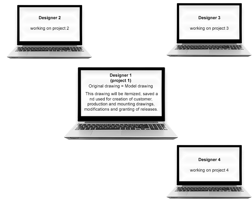
If the model drawing is a small one, the project can be handled within one model drawing. All assemblies and parts will be processed in one model drawing, they will be itemized and saved there. Customer drawings, production drawings and mounting drawings will be created, released ans saved based on this model drawing.

|
Unambiguous item numbers in the original drawing |

|
Derived drawing(s) can only be created after completion of all assemblies. |
|
|
If this method has been chosen, no other engineers can work simultaneously on the model drawing! |
 Example 1: Creating Assemblies and Deriving Drawings in Original Model Drawing.
Large model drawings / Simultaneous working with referenced detail drawings
If you are dealing with large and complex model drawings it often makes sense to split the large model drawing into several smaller ones (Concurrent Engineering). This improves efficiency and allows a working of several engineers on one project.
For this purpose, the original model drawing will be subdivided into suitable structure assemblies and saved in a non-itemized state. To define an assembly as a structure assembly, use the Part attributes function ion the context menu of the assembly. In the dialogue window, choose Part type: Structure assembly. Structure assemblies will be marked with the  symbol in the part structure of the ICN. Further information on structure assemblies can be found in the What are Structure Assemblies? topic.
The structure assemblies of the model drawing are saved separately as externally referenced detail drawings.
Next, one can choose between the following two procedures:
- Change, itemisation and drawing derivation in the individual model drawings
- Working in the detail drawings - Itemization and drawing derivation in the original model drawing
Change, itemisation and drawing derivation in the individual model drawings
The original drawing is split into suitable structure assemblies and saved in a non-itemized state. To be on the safe side, the itemisation in the original drawing can also be prevented by deactivating the Itemisation checkbox in the document master of the original drawing (document attribute ITEMISATIONMODEL). As a result, the original model drawing will not be an itemized source model.
The structure assemblies of the model drawing are saved individually as externally referenced detail drawings. These referenced detail drawings can then be edited and itemized on different workstations. Customer drawings, production drawings and mounting drawings are created, released and modified in the detail drawing. Changes to the detail drawings are, of course, also transferred to the original model drawing due to referencing. In the process, the original model drawing serves only the purpose of providing an overview.
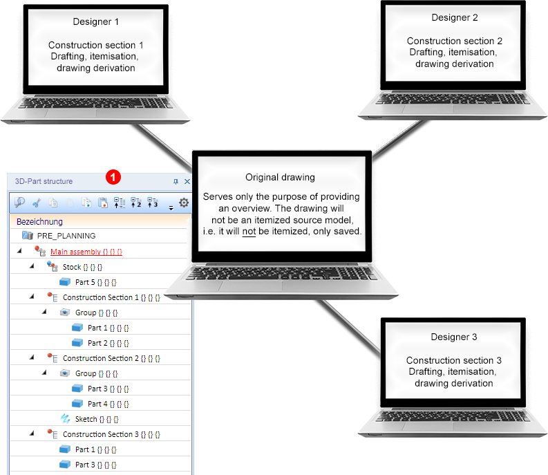
(1) shows the structure in the HiCAD ICN with structure assemblies. These are externally referenced, namely, as detail drawings.
If this method has been chosen, the model drawings called Construction section 1, Construction section 2 and Construction section 3 will be itemized independently from each other (identical part search takes place per Construction section). Therefore, the responsible engineers should inform each other about the start values they intend to use in the itemisation settings. Otherwise it might happen that non-identical parts will have identical item numbers (e.g. 100) when taking a look at the drawings for the whole project later.
This can be avoided by reserving a specific range of item number for each of the individual model drawings (Construction sections 1 - 3).
|
|
The editing of the assemblies can take place at the same time at different workstations. After completing an assembly the corresponding drawings can be derived immediately. |
|
|
In the original drawing, identical parts may have different item numbers. |
This method is described in detail in Example 2a.
Working in the detail drawings - itemization and drawing derivation in the original model drawing
The original model drawing is split into suitable structure assemblies and saved in a non-itemized state. The structure assemblies are saved individually as externally referenced detail drawings. These externally referenced detail drawings can then be edited and saved - but not itemized - on different workstations. After completion of all structure assemblies the original model drawing will be updated. Itemisation of all structure assemblies and drawing derivations will then take place in the original model drawing; that is, the original model drawing serves as the itemized source model here.
To be on the safe side, the itemisation in the detail drawings can also be prevented by deactivating the Itemisation checkbox in the document masters of the detail drawings (document attribute ITEMISATIONMODEL). As a result, the detail drawings will be no itemized source models.
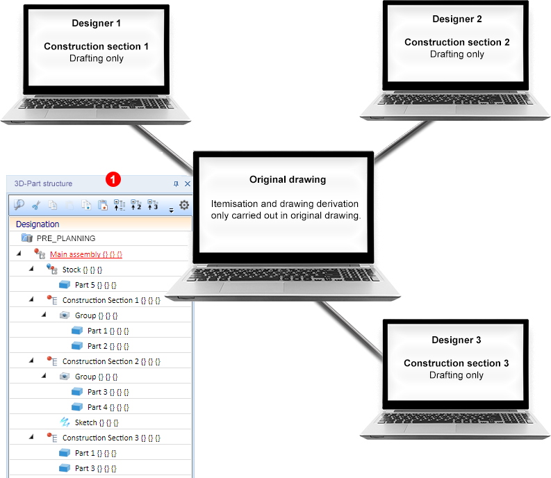
(1) shows the structure in the HiCAD ICN with structure assemblies. These are externally referenced, namely, as detail drawings.
If this method has been chosen, the model drawings called Construction section 1, Construction section 2 and Construction section 3 will only be saved, but not itemized. Itemization will only take place in the original model drawing.
However, please note that productions drawings etc. can only be derived in the original model drawing.
|
|
The editing of the assemblies can be distributed among different workstations. |
|
|
The item numbers in the original model drawing are unambiguous. |
|
|
Drawing derivation in the original model drawing can only take place after completion of all assemblies. |
This method is described in detail in Example 2b.
Deriving construction sections during designing
This approach is interesting for companies that want to create construction sections during the design process. In this case it is important that both the part structure of the model drawing in the ICN and the definition of the itemised source model are set up correctly beforehand.
To do this, proceed as described below (example of a new model drawing).
- Create a new project or activate an existing project via the corresponding function on the Management + BIM tab.
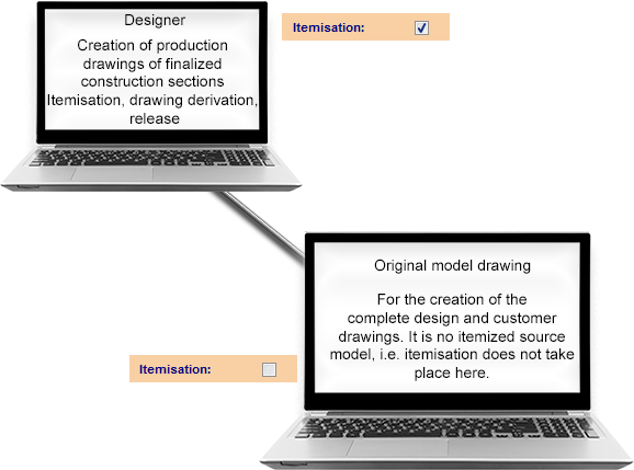
- Use the Management + BIM tab to create a model drawing with a new article master, document master and a main assembly. In the document master window, the Itemization checkbox must be deactivated (the checkmark must not be greyed out, it must be completely removed!).
- Create a structure assembly below the main assembly. Save it as an externally referenced detail drawing. Make sure that the Itemization checkbox is activated in the document master.
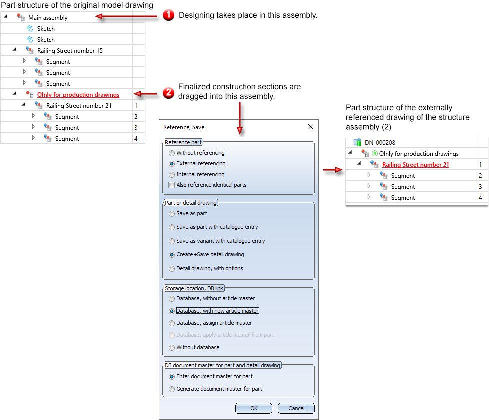
- Work in the original model drawing (without itemised source model) as usual. The customer drawings - for approval by the architect or customer - should also be created there. If the approval is granted, the corresponding construction section in the ICN is simply moved to the structural assembly (in the example Only for production drawings) by Drag & Drop.
- The externally referenced drawing of this structural assembly can then be opened. There, start the itemization, save the model drawing and create the production drawings. When the production drawings are complete, the corresponding parts must be set to Checkup or Released. This "locks" the item numbers and prevents the BOMs from changing. If at a later date drawings of identical parts are created from which production drawings already exist, they will be assigned new item numbers.
|
|
The same itemization settings can also be used for larger projects. |
|
|
The item numbers are unique. |
|
|
Any number of CAD engineers can work on the same project. |
|
|
It is essential to pay attention to the Checkup and Released locks. This is very important for the BOMs. |
|
|
It is important to make sure that the externally referenced drawing of the structural assembly (in the example Only for production drawings) only contains parts without locks when creating a revision index. |
|
|
Identical parts receive different item numbers - but this is intended anyway in most cases. |

Requirements for a Smooth Operation (ManBIM) • Important Information (ManBIM) • Overview of Functions (ManBIM) • Examples (ManBIM)