You can additionally influence the behaviour of the production drawing generation via the Configuration Editor (ISDConfigEditor.exe in the HiCAD EXE directory). The relevant settings can be found at PDM > Management + BIM > Production drawings.
The following parameter settings are available:
Production drawings
Mounting drawings

Depending on the corresponding feature entries, you distinguish between processed and unprocessed beams in your model drawing. For example, a lengthening, trimming, or moving points in a rectangle will not make the beam a "processed" beam. All other functions, e.g. as bores, subtractions, notches etc. on a beam will make the beam a "processed" beam.
Via the parameter Production drawing for unprocessed beams you can now specify whether "unprocessed" beams are to be considered for derived drawings or not.
The following settings are possible:
Handling of unprocessed beams depending on later machine processing
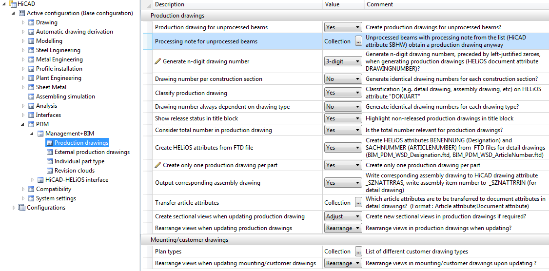
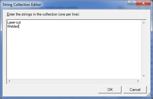
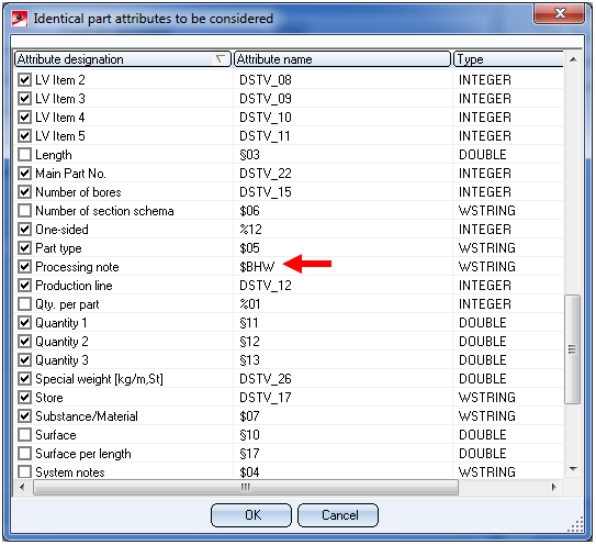
The drawing creation for unprocessed beams can also be controlled depending on later machine processings. For this purpose the HiCAD attribute Processing note $BHW is available. For instance, you can achieve via this attribute that a production drawing is created for unprocessed beams that need to be laser-cut, despite the current Production for unprocessed beams setting. For this to happen, the corresponding processing notes must be entered into the Collection Box of the Processing note for unprocessed beams parameter, e.g.:
The following additional adjustments are required:
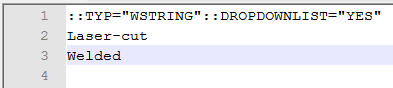
It is important that the spelling of the texts must be identical with those in the Collection Box (please also attention to case-sensitivity!).
 > ... with options
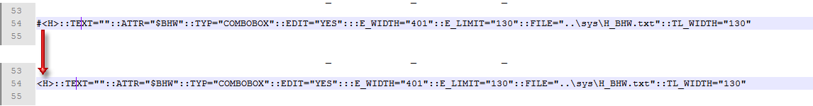
  and, in the dialogue window, click the Configuration button. In the displayed window, activate the attribute $BHW:
 Important note on Sheet Metal parts
One distinguishes between sheets with identical cross-sections (unprocessed sheets) and processed beams. If desired, you can suppress the output of sheets with identical cross-sections in the workshop drawing. To do this, choose Sheet Metal and activate the Suppress productions drawings for sheets with identical cross-sections... checkbox. The checkbox is deactivated by default. Click here for further information.
If you change this setting in the Configuration Editor, already itemized sheets need to be re-itemized and saved!
If you want an n-digit drawing number (padded with zeroes from the left) to be generated when creating production drawings, select the number of desired digits here. The n-digit drawing number will be assigned to the HELiOS document attribute DRAWINGNUMBER.
At the same time a text that is composed of the project name and the drawing number, separated by a "-" (e.g. EXAMPLEPROJECT-00005) will be assigned to the document attribute DRAWINGNUMBER_TEXT.
The default setting is 3-digit.
If you select the generation of an n-digit drawing number here, you can use the parameter Drawing number per construction section to determine whether the numbering is to be consecutive spanning all construction sections, or consecutive within each construction section.
Similarly, you can select via the parameter Drawing number always dependent on drawing type whether the numbering is to be consecutive spanning both the production drawings and the mounting drawings, or separately for production drawings and mounting drawings.
The attribute DRAWING_NUMBER can also be configured individually if required. For this purpose the template file BIM_PDM_DrawingnumberGeneration.ftd is available that can be edited with the Templates, Attribute assignment function (Steel Engineering > Settings > ...).
Use the Document attribute Construction section (CONSTRUCTION_SECTION) to identify assemblies as individual construction units. If this attribute has been assigned via the document master to an assembly, all parts that belong to it in there will obtain the link "Construction unit". In this way you can check at any time to which assembly a part actually belongs.
If you have selected the Generation of n-digit drawing numbers you can specify here whether the numbering has to take place consecutively spanning all construction sections (No) or consecutively within one construction section (Yes).
The default setting is No..
Use this parameter to specify whether the value Production drawing is to be assigned to the HELiOS attribute Document type (DOKUART) in drawings created with the Management + BIM module (No) or if you want a distinguishing between detail drawing, assembly drawing, etc. (Yes). The default setting is Yes.
To ensure that the attribute DOKUART will be shown in the HELiOS masks and result lists you need to adjust them accordingly.
If you have selected the Generation of n-digit drawing numbers you can determine here whether you want a consecutive numbering spanning all production drawings (assembly drawings, beam detail drawings, plate detail drawings,etc.) and mounting drawings (No), or prefer a separate numbering for production drawings and mounting drawings (Yes).
The default setting is No.
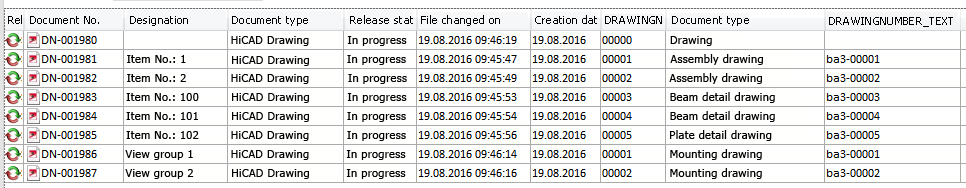
Example: Drawing number always dependent on drawing type = Yes
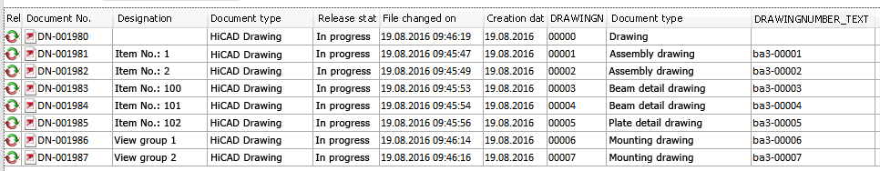
Example: Drawing number always dependent on drawing type = No
If you want non-released drawings to be marked in the title block, set this parameter to Yes. This is also the default setting. The title blocks of non-released drawings will be marked with an "in progress" note in the title block.
This marking requires the use of the _SZNATTRSTA attribute.
Here you can specify whether the total number of parts is change relevant for the production drawing.
The default setting is Yes.
If you want to generate the HELiOS attributes BENENNUNG (Designation) and SACHNUMMER (Article number) for detail drawings from template files , set the parameter to Yes.
In this case, the attributes for assemblies, beams, general parts, Sheet Metal parts and Steel Engineering plates will be generated according to the corresponding template file.
|
Template file |
Settings for the |
Pre-setting |
|
BIM_PDM_WSD_Assembly_ArticleNumber.ftd |
Configuration of the HELiOS document attribute SACHNUMMER (Article number) for detail drawings of assemblies (assemblies with one main part) |
{Total quantity (Part attribute)} x {Article number (Part attribute)} |
|
BIM_PDM_WSD_Assembly_Designation.ftd |
Configuration of the HELiOS document attribute BENENNUNG (Designation) for detail drawings of assemblies (assemblies with one main part) |
%TS(TEXTE_STB401) {Item number (Part attribute)} %TS(TEXTE_STB401) stands for the content of the text key STB_401 which is the text Item No.: |
|
BIM_PDM_WSD_Beam_ArticleNumber.ftd |
Configuration of the HELiOS document attribute SACHNUMMER (Article number) for detail drawings of beams |
{Total quantity (Part attribute)} {Article number (Part attribute)} x{Länge (Part attribute)} |
|
BIM_PDM_WSD_Beam_Designation.ftd |
Configuration of the HELiOS document attribute BENENNUNG (Designation) for detail drawings of beams |
%TS(TEXTE_STB401) {Item number (Part attribute)} |
|
BIM_PDM_WSD_Multi_Designation.ftd |
Configuration of the HELiOS document attribute BENENNUNG (Designation) for detail drawings of multi-part beams |
%TS(TEXTE_STB401) |
|
BIM_PDM_WSD_Part_ArticleNumber.ftd |
Configuration of the HELiOS document attribute SACHNUMMER (Article number) for detail drawings of general parts |
{Total quantity (Part attribute)} x {Article number (Part attribute)} |
|
BIM_PDM_WSD_Part_Designation.ftd |
Configuration of the HELiOS document attribute BENENNUNG (Designation) for detail drawings of general parts |
%TS(TEXTE_STB401) {Item number (Part attribute)} |
|
BIM_PDM_WSD_SheetMetal_ArticleNumber.ftd |
Configuration of the HELiOS document attribute SACHNUMMER (Article number) for detail drawings of Sheet Metal parts |
{Total quantity (Part attribute)} x {Article number (Part attribute)} x{Length of 2-D development (Part attribute)} x{Width of 2-D development (Part attribute)} |
|
BIM_PDM_WSD_SheetMetal_Designation.ftd |
Configuration of the HELiOS document attribute BENENNUNG (Designation) for detail drawings of Sheet Metal parts |
%TS(TEXTE_STB401) {Item number (Part attribute)} |
|
BIM_PDM_WSD_SteelPlate_ArticleNumber.ftd |
Configuration of the HELiOS document attribute SACHNUMMER (Article number) for detail drawings of Steel Engineering plates |
{Total quantity (Part attribute)} x {Article number (Part attribute)} x{Length(Part attribute)} x{Width(Part attribute)} |
|
BIM_PDM_WSD_SteelPlate_Designation.ftd |
Configuration of the HELiOS document attribute BENENNUNG (Designation) for detail drawings of Steel Engineering plates |
%TS(TEXTE_STB401) {Item number (Part attribute)}
|
Use the Templates, Attribute assignment function (Steel Engineering > Settings > ...) to adjust the templates individually for attribute assignment.
If you want only one production drawing to be created per part when performing a drawing derivation, set this parameter to Yes.
When generating detail drawings, you can automatically transfer the document number of the assembly's single part as well as the assembly item number to the title block. For this to happen, you need to set the parameter Output corresponding assembly drawing to Yes (default setting is No.) In this case, the HiCAD drawing attribute SZNATTRAS will be assigned the corresponding assembly drawing name(s), the attribute _SZNATTRRRIN will be assigned the item number of the assembly, and will be displayed in the title block of the detail drawing.
A prerequisite for this is that a corresponding title block exists in which the drawing attribute _SZNATTRAS and _SZNATTRRRIN, respectively, can be displayed. The chapter Basics > Drawing Objects > Drawing Frame and Title Block explains in detail how to change title blocks and use variables in them.
 This only applies to detail drawings.
When generating detail drawings with the Management + BIM functions you have the option to transfer article attributes of the semi-finished products to the document attributes of the detail drawings. Such document attributes can, for instance, be used in the HELiOS result lists as filters or search criteria.
To transfer article attributes of the semi-finished product to the document attributes of the detail drawing, click on the  icon and define the desired assignments. Each assignment is defined in one row and is composed like this:
Article attribute;Document attribute
If, for instance, you want to assign the Artcle attribute BENENNUNG (Designation) to the Document attribute BEMERKUNG (Comment) of the detail drawing, the assignment must look like this:
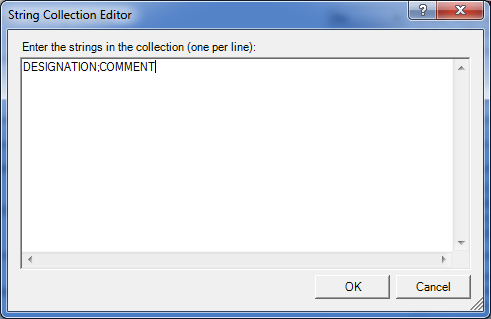
Use this parameter to specify for external, PDM-managed drawings whether missing sectional views are to be created when you update the derived drawing.
The default setting is Do not adjust.
Besides the creation of mounting, workshop and production drawings you can use the Customer drawing function to create various customer drawings for approval, e.g. builders' or architects' plans. You can specify the drawing types that are to be offered for selection via the Plan types parameter.
Pre-set has been the Customer drawing plan type (Text key STB_HELIOS_CUSTOMER_DRAWING). If you want to define other types, click the symbol in the Collection field, enter the name of the new drawing/plan type in a new line, e.g.:
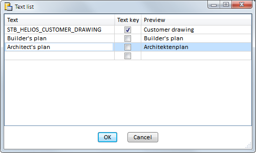
Confirm with OK.
Use this parameter to specify for external, PDM-managed drawings whether you want the views to be rearranged automatically in production drawings or mounting drawings upon updates. Switching this option off makes sense if, for instance, you have deliberately moved some views and want to keep their new position.
The default setting is Rearrange.

Requirements for a Smooth Operation (ManBIM) • Management + BIM Settings in the Configuration Editor (ManBIM) • Important Information(ManBIM)
|
© Copyright 1994-2018, ISD Software und Systeme GmbH |