Basics - What's New?

Discontinuations
Discontinuation of Windows® 7 and Windows® 8Microsoft® has discontinued support for the Windows® 7 operating system in January 2020. For compatibility reasons, HiCAD 2020 SP2 and HELiOS 2020 SP2 were the last versions of our CAD or PDM system to support Windows© 7. HiCAD 2021 and HELiOS 2021 no longer run under Windows© 7, Windows© 8 and the corresponding server operating systems (Windows Server 2008 R2, Windows Server 2012 and older) are also no longer supported. If an attempt is made to install HiCAD 2021 or HELiOS 2021 on a computer with Windows© 7 or Windows© 8, a message appears.
|
Discontinuation of "old" HiCAD itemizationAs of HiCAD 2019 the “old” itemisation, i.e. the itemisation that was used up to HiCAD 2017, will only be available for model drawings that were already itemized with these functions. From HiCAD 2021 onwards, only the “new” itemization will be supported. Please also read the information given in the Conversion of Old Itemisations topic.
|
Discontinuation of "old" OpenGL versionsFrom HiCAD 2021 on, only OpenGL version 4.3 is used in all HiCAD modules. Until now this was only the case with the module HiCAD Point Cloud. This means that HiCAD 2022 can no longer be run on computers without a separate graphics card. To avoid possible problems with onboard graphics cards, we recommend using a stand-alone graphics card.
|
Discontinuation of old figure format (FIG)The following notes regarding FIG-FGA conversion are unnecessary if HELiOS is used in conjunction with the HELiOS Vault Server. Since HiCAD 2017 we support FGA as figure format (before that FIG). From HiCAD/HELiOS 2021 or HELiOS 2021 as an update for HiCAD 2019/2020 onwards, we require that all figures stored with HELiOS have been converted to the new FGA format beforehand. To convert existing 2-D FIG files, the tool Converter_FIG_To_FGA.exe is available in the exe directory of the HiCAD installation. If there are still unconverted FIG files in the HELiOS document database at the time of the database update, you will be informed of the outstanding conversion of these files before the database update. In this case, the conversion must be carried out before or at the latest directly after the update using Converter_FIG_To_FGA.exe.
|
Discontinuation of the "old" Create detail drawing functionWith the release of HiCAD 2012, the previously valid workshop drawing functionality in Steel Engineering had been extended to a function for general drawing derivation. The previous functions for detail drawings in Steel Engineering were still available in the Detail drawing section of the Drawing menu. As of HiCAD 2022 (Version 2700.0) these functions are no longer supported.
|
Discontinuation of HELiOS 32-Bit and HiCAD Viewer 32-BitAs of HELiOS 2022 (Version 2700.0), a 32-Bit version for HELiOS and the HiCAD Viewer will no longer be available. However, the interface to 32-Bit applications such as Office will still be possible and is not affected by the discontinuation of the 32-Bit installation of HELiOS.
Discontinuation of CADENAS PARTdataManagerAs of HiCAD 2022 SP2, the CADENAS PARTdataManager will no longer be supported. Thus, the functions Insert main part, PARTsolutions (CADENAS program) and Import PARTsolutions part will no longer be available from SP2 onwards.
Discontinuation of 3-D projection gridAs of HiCAD 2023, the 3-D projection grid function is no longer available. |
Service Pack 2 2023 (V 2802)
Automatic data save with higher performance
As of SP2, when using the automatic data save, the polygon models of parts are no longer saved, but are only recalculated when a drawing is restored. This improves the performance of automatic data save for drawings with very many parts
The behaviour can be influenced in the Configuration Editor at System settings > Data save via the checkbox Quick data save The checkbox is active by default
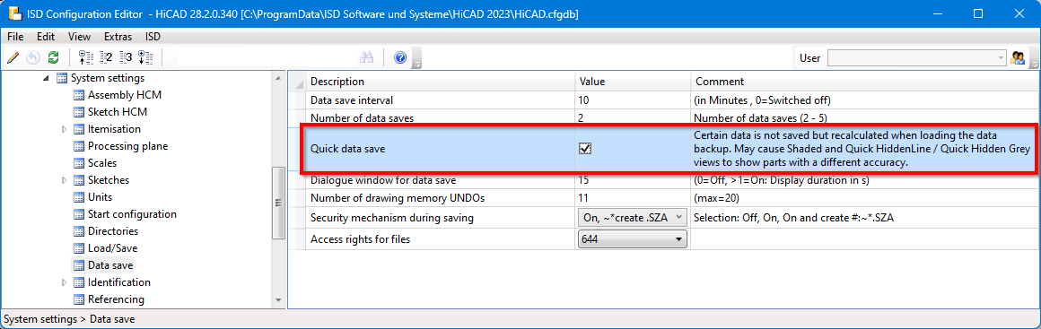
Please note the following:
-
The polygon models of reduced loaded parts are always saved - regardless of whether the checkbox is active or not.
-
In rare cases it can happen that users change the display accuracy of individual parts. In this case, the representation would have to be re-adjusted after the restoring. If you work specifically and frequently with display accuracy, you should deactivate the checkbox.
Itemisation
Itemisation - minor text changes
The term "Itemisation mode Standard" has been replaced in SP2. In this context, the function "Switch to standard itemisation" has been renamed Switch from itemisation up to HiCAD 2017.
In addition, texts have been adapted in Configuration Editor at System settings > Itemisation or System settings > Itemisation > Migration:
| up to HiCAD 2023 SP1 | as of HiCAD 2023 SP2 |
|---|---|
|
Presettings that are entered as drawing properties when fixing the itemisation mode Standard.. |
Default settings are entered in the drawing properties in the first situation in which they become relevant. |
|
When switching to the itemisation mode Standard, use the stored default settings. |
When switching from the Itemisation up to HiCAD 2017, do not perform a conversion, but use the stored default settings. |
Itemisation - HELiOS Article reference attributes
As of SP2, the article reference attributes defined in HELiOS can also be used as a sort criterion in itemisation, for example Tensile strength. These are offered in the selection list on the Attributes tab when adding and editing attributes.
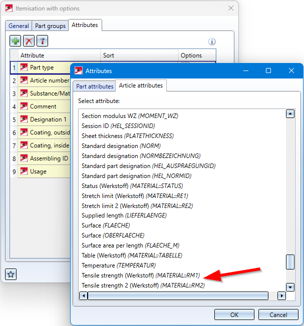
In practice, frequently used article reference attributes are
-
Customer,
-
Material and
-
Manufacturer.
Note that if you have not already done so, you must first define these as reference attributes in HELiOS.
Itemisation - Sort numbers
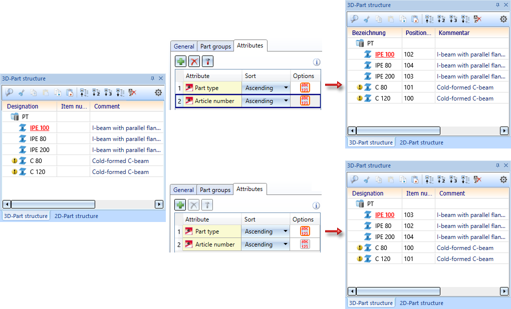
In practice, a sorting is often desired in which the numbers are not sorted as text, i.e. alphabetically, but as numbers. Therefore, as of SP2, it is possible to specify for many attributes how the sorting should be done for the respective attribute. For this purpose, the Attributes tab has been adapted accordingly. New is the column Options, in which you can select the sorting mode by clicking on the corresponding symbol:
|
|
Compare digits like letters Example: IPE 100 < IPE 80 |
|
|
Compare numbers as a whole Example: IPE 80 < IPE 100 |

The default setting as of SP2 is Compare numbers as a whole  .
.
A simple example:
![]() Please note:
Please note:
- The setting of the sorting mode Compare numbers as a whole is lost if the drawing is opened and saved with HiCAD 2023 Version 2801.X or 2800.X.
- If a drawing is loaded that contains itemisations from an earlier HiCAD version (before HiCAD 2023 SP2), the settings used there are active.
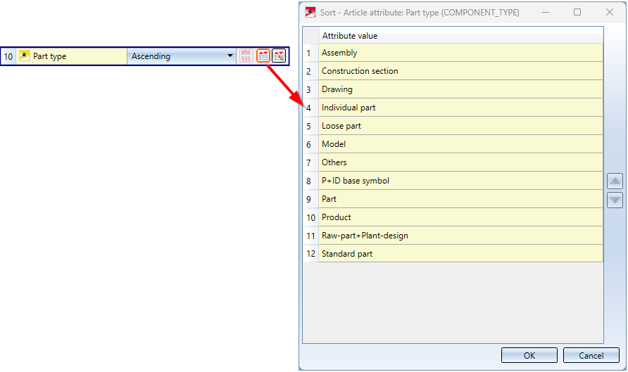
Itemisation - User-defined sorting for HELiOS attributes with Predefined lists
Item numbers can also be sorted by HELiOS attributes with Predefined lists. Until now, however, the order resulted from the alphabetical order of the language-dependent texts. As of SP2, it is now possible to change the order individually. For this purpose, two new icons are available on the Attributes tab.
 Sort alphabetically
This icon is only displayed for HELiOS attributes with Predefined lists. These are multilanguage attributes, such as the part type (COMPONENT_Type) and - if defined accordingly in HELiOS - string or integer attributes. With a click on the icon you switch from alphabetical sorting to user-defined sorting. The icon representation changes to  . In this case, the Determine user-defined order
  icon is also displayed.
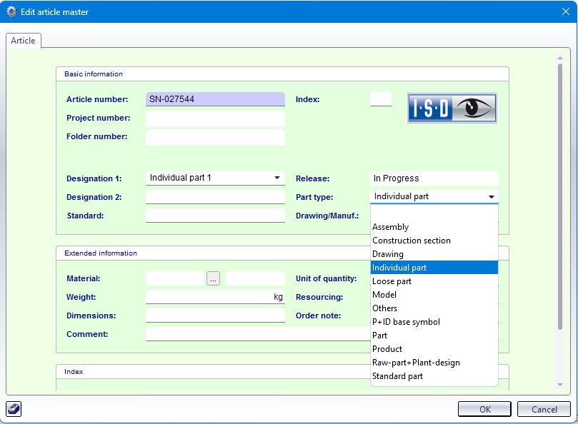
Determine user-defined order
With a click on the symbol you can individually change the sortting order for HELiOS attributes with Predefined lists, e.g. for the article attribute Part type (COMPONENT_TYPE):
Behaviour of BOMs when updating derived drawings
BOMs that are aligned to the drawing frame (option Quantity list in drawing frame.../Structure list in drawing frame...) are only rearranged when updating derived drawings if the views are also rearranged. This means that the checkbox Rearrange views must be active.
If no rearrangement takes place, HiCAD still ensures that the fixed point of the BOM corresponds to the settings of the drawing derivation.
Example:
If the BOM is arranged in the top right corner, then the top right corner of the BOM will still be in the top right corner of the view frame. If the BOM has become longer or wider, then - to ensure this - it is moved if necessary.
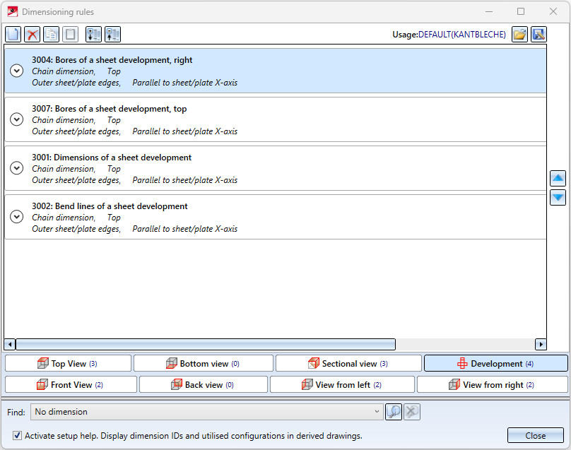
Dimensioning Rules Editor - Development view
In the Dimensioning Rules Editor, as of SP2, the rules for the development view of Sheet Metal parts can also be defined. For this purpose, the dialogue window has been extended by a corresponding tab.
Please note:
In the drawing derivation, these rules are only taken into account if the options for dimensioning are activated accordingly in the settings for sheet developments, e.g. like this: 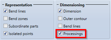
New dimensioning rules for agraffes
There are new dimensioning rules for agraffes:
- Dimension agraffes in Sheet Metal parts via dimensioning point (163)
- Dimension agraffes in Sheet Metal development via dimension point (3016)
For the two dimensioning rules, an isolated point was added to the agraffe in the bore pattern. This point serves as a dimensioning point and has the designation Dim.
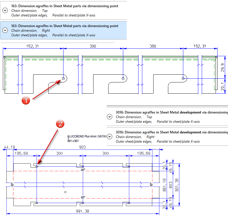
(1) Dimensioning point of the agraffe in the sheet, side view from left; (2) Dimensioning point of the agraffe in the sheet development
ICN Part structure display with grid lines
To further emphasize the levels of the part structure, grid lines can be displayed by activating this checkbox.
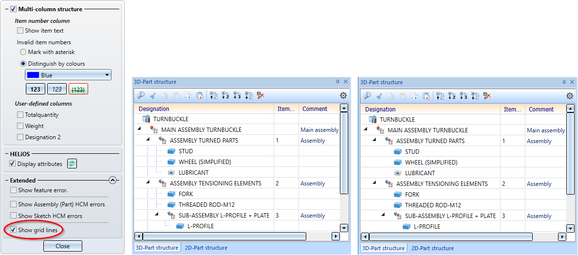
Left: with grid lines, Right: without grid lines
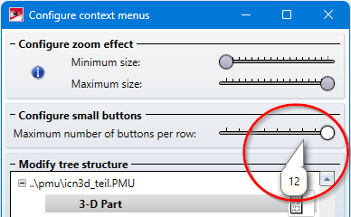
Customise context menus
The Maximum number of buttons per row in the context menus for parts etc. is now preset to 12. This only applies to new installations. Customised menus do not change during an update installation.
Change assembly coordinate system
Like every part, an assembly also has a part coordinate system. Until now, this coordinate system could either be determined automatically by HiCAD or by you when creating the assembly. A corresponding parameter is available in the Configuration Editor at Modelling > Part creation > Assembly.
As of HiCAD 2023 SP2 you can also move the part coordinate system of assemblies with the new function Change assembly coordinate system  (Drawing > Others > World CS
  > ...).
Note that this can also change the geometry and position of the parts in the drawing. Referenced parts will change at all points of use.
Please also see the examples for Feature and Parametrics.
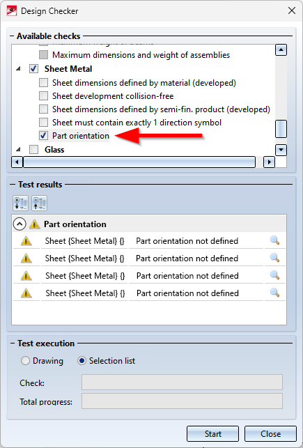
Extension of the Design Checker for Sheet Metal parts
By setting the part orientation you can determine which view of a part should be the front view or the top view. This is also evaluated when creating the production drawings. Since SP1 it is possible to check for Sheet Metal parts during the creation of the production drawings whether the part orientation has been set accordingly. To do this, the checkbox Check part orientation for Sheet Metal parts must be activated in the Configuration Editor at Automatic drawing derivation > Production drawing.
As of SP2, this can also be checked via the Design Checker - independent of the setting in Configuration Editor. The Design Checker has been extended accordingly.
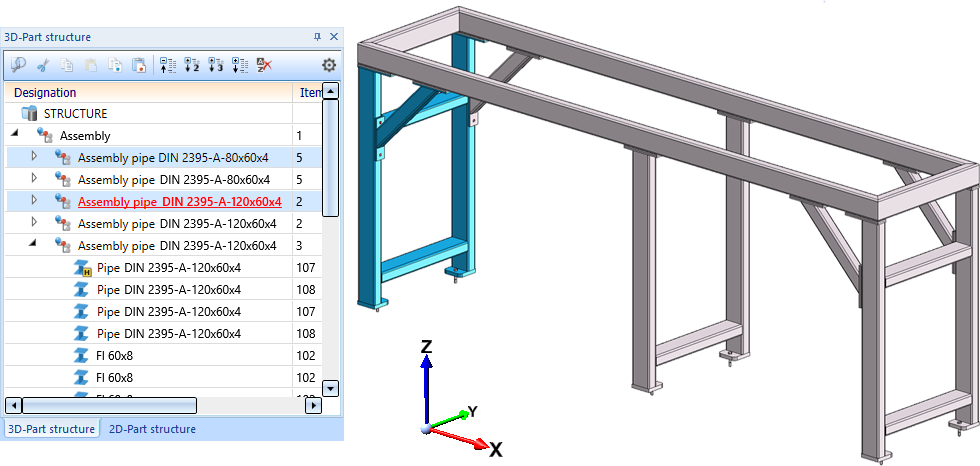
Updating mounting drawings
When updating mounting drawings that were created with the setting
 New view group via active assembly(-ies)
only the parts of the view group that belong to the selected assemblies are taken into account from SP2 and not all parts that lie within the bounding box.
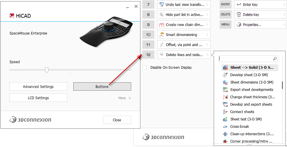
Support of the new SpaceMouse®
When working on 3-D drawings, you can use a SpaceMouse®in addition to the standard mouse. HiCAD supports the current models from 3Dconnexion. To connect to HiCAD, install the current software 3DxWare from 3Dconnexion GmbH on your computer.
By pressing, pulling, rotating and tilting the controller cap (control knob), you can rotate, move and enlarge or reduce your 3-D drawing in HiCAD, regardless of the SpaceMouse type. The navigation in the Object Mode of the SpaceMouse® behaves as if you were reaching for the 3-D part and holding it in your hand.
The rotation point for stabilising the rotation is automatically placed on the nearest part. If you move the standard mouse, the rotation point also changes.
The MENU button on the SpaceMouse® or 3Dconnexion Home (on your Desktop) will take you directly to the 3Dconnexion Settings. Via Advanced Settings you can configure the default behaviour of the controller cap in HiCAD.
Some HiCAD functions (such as Save drawing) are pre-assigned to the buttons of the SpaceMouse®. With the SpaceMouse® Enterprise, the HiCAD functions are shown with text and icon in the display of the mouse. To customise the function keys for your company, call up the 3Dconnexion Settings. Then click on Buttons. Click on the arrow  next to the function name and select a different HiCAD function. Click on Close to save the new assignment of the function button.
HiCADGUIReset - Restore defaults
The functions of HiCADGUIReset can now also be executed automatically by specifying various options, i.e. without displaying the dialogue window.
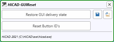
Analogous to the functions of the dialogue window, the following options are possible:
|
Option |
Effect |
Example |
|---|---|---|
|
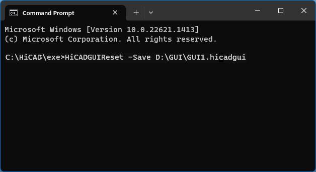
-Save Dateiname |
Save GUI settings |
HiCADGUIReset -Save D:\GUI\GUI1.hicadgui |
|
-Load Dateiname |
Load GUI settings |
HiCADGUIReset -Load D:\GUI\GUI1.hicadgui |
|
-ResetAll |
Restore DUI delivery state |
HiCADGUIReset -ResetAll |
|
-ResetIDs |
Reset button IDs |
HiCADGUIReset -ResetIDs |
Service Pack 1 2023 (V 2801)
Product extension
The Coating function is now also part of the basic HiCAD creator and HiCAD solution models. This means that the function is also available in all industry suites.
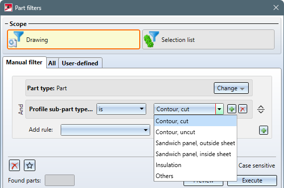
Part filter extension
The Find  function in the transparent toolbar has been extended to include filters for profile installation. With the new rule Properties > Profile sub-part type (Profile Installation) the sub-part types
- Contour, cut,
- Contour, uncut,
- Sandwich panel, outside sheet,
- Sandwich panel, inside sheet,
- Insulation and
- Others, e.g. sealing chords.
can be easily selected.
.
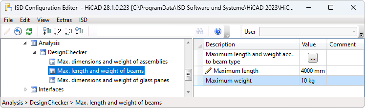
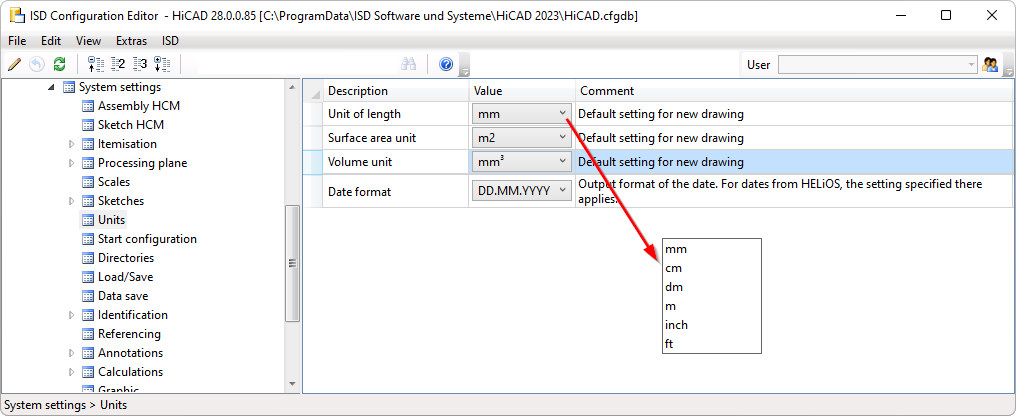
Units in the Configuration Editor
In the Configuration Editor, under Extras, you can set whether the values specified there for length and weights should be displayed in metric units (millimetres and kilograms) or in imperial units (inches and pounds).
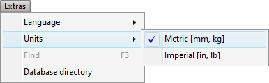
The numbers are displayed rounded, with the unit following. If the values are edited, no rounding will occur, but the numbers will be displayed exactly.
Examples:
If the setting under Extras is changed, the values will be converted accordingly, e.g.
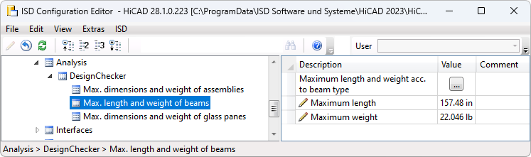
The setting of the units of measurement under Extras only affects the display in the Configuration Editor. When drawing in HiCAD, the values are always converted to the unit of measurement of the drawing.
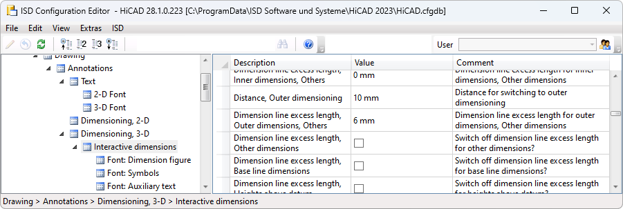
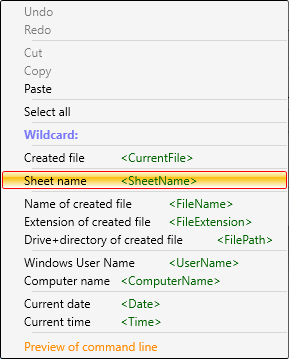
Sheet name - Placeholder during printing
In the printer output there is now a placeholder for the Sheet name called <SheetName> which can be used in the XPS and the ISD FilePrinter output to generate the file name. For this purpose, the context menu under Postprocessing Command line has been extended on the PS/XPS Settings tab.
This concerns the functions
 Drawing > Save/Print > Print > Active drawing and
 Drawing > Save/Print > Print > Selected model drawings.
Examples:
- C:\Program Files\gs\gs9.54.0\bin\gswin64c -dNOPAUSE -dBATCH -dPDFA -sDEVICE="pdfwrite" -sOutputFile="<FilePath><SheetName>.pdf" <CurrentFile>
- C:\Program Files\gs\gs9.54.0\bin\gswin64c -dNOPAUSE -dBATCH -dPDFA -sDEVICE="pdfwrite" -sOutputFile="<FilePath><FileName><SheetName>.pdf" <CurrentFile>
.
Regarding the Sheet name, i.e. the placeholder <SheetName>, please note the following:
-
All not allowed characters are replaced by an underscore _ in the sheet names. Not allowed characters are:\:/\"<>?*|.
-
If the sheet names are the same, a new name will be generated automatically, e.g. MySheet -> MySheet(2) -> MySheet(3) ...
-
For merged PS files, the name is composed of the output sheet names (separated by commas). The length is limited to 32 characters. E.g. MySheet1,MySheet2,MySheet3.pdf
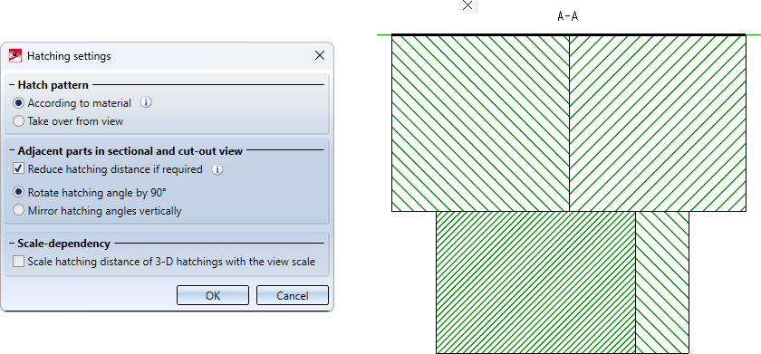
Hatching settings
New under Drawing > Properties is the Hatching settings  function.
Use this function to define the default settings for the hatching of cut surfaces created by sectional views, cut-outs and detail views. The settings apply to hatchings in the current drawing and are saved together with the drawing.
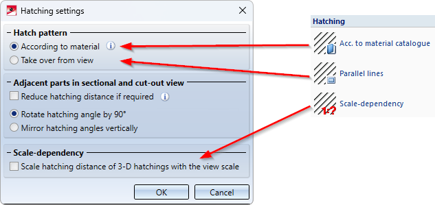
The previous functions
- Acc. to material catalogue,
- Parallel lines and
- Scale-dependency
have been integrated into the new function.
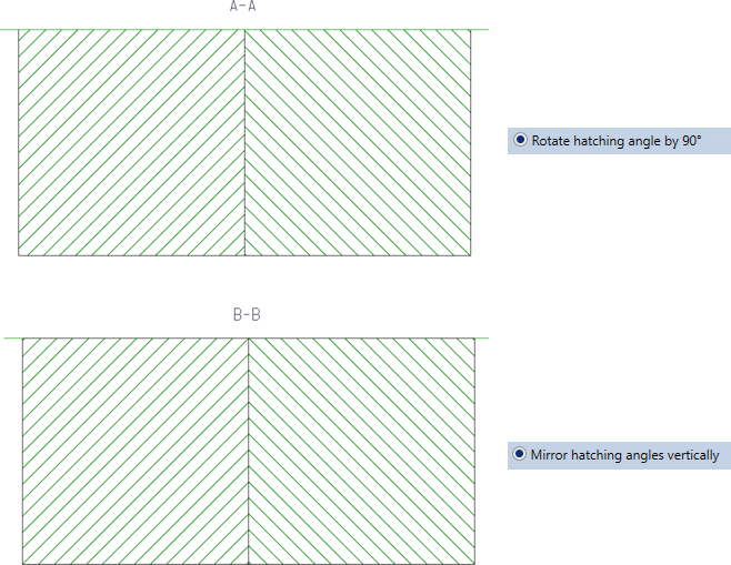
A new feature is that it is now possible to specify how neighbouring parts are to be visually delimited from each other in a sectional view. This can be done by rotating the hatching angle or by vertical mirroring.
Sometimes, however, changing the hatching angle is not sufficient to clearly delimit neighbouring parts from each other. This can be the case, for example, when several parts touch each other (see example). If the Reduce hatching distance if required checkbox is active, the hatching distance is also used for delimitation. This means that the hatching distance of individual parts is reduced.
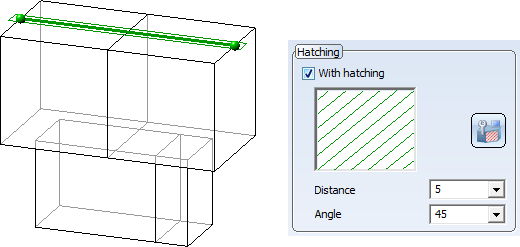
Example
We consider four cuboids that touch each other. We want to create a sectional view with the sketch shown as the section path.
The following image shows that not all parts can be clearly distinguished from each other using only the hatching angle.
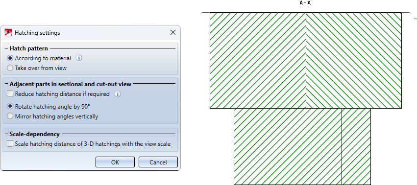
In this case, it is recommended to activate the Reduce hatching distance if required checkbox.
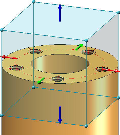
Easier identification of plug-in arrows
The plug-in arrows - as used, for example, when defining a detail view of type cuboid or when clipping point clouds - are now easier to identify. The arrows are already identified when the cursor is in the "vicinity".
Mounting drawing - View group above assemblies
When creating mounting drawings, it is now possible to create the view group above the active assembly or the selected assemblies.
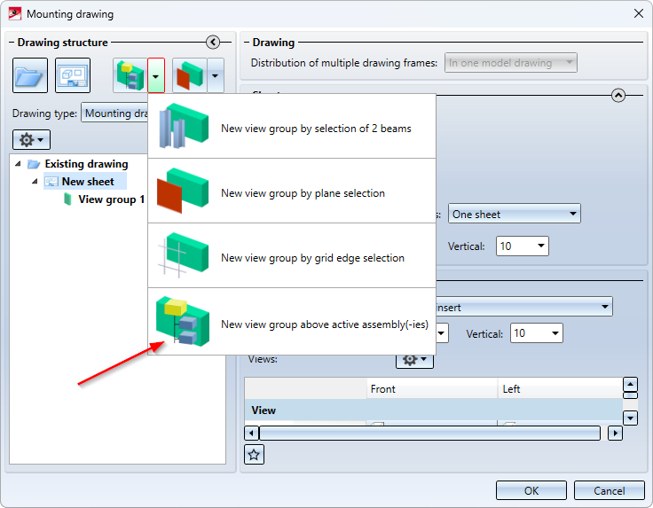
The view group is determined by selecting/defining a processing plane when calling the function for the active assembly or the selected assemblies. The same options are available for selecting/defining the plane as for the 3-D processing plane function. The box is created by extruding the processing plane to the front and back - considering the offset specified in the extended settings. The size of the box is determined here by the active assembly or the selected assemblies when the function is called.
Example:
A mounting drawing of the two selected assemblies is to be created.
The XZ plane of the world CS is selected as the plane.

Result:
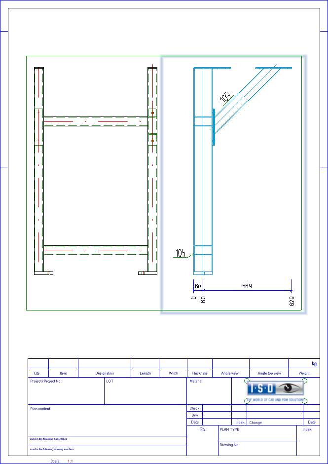
Derived drawings - Check part orientation for Sheet Metal parts
By setting the part orientation you can determine which view of a part should be the front view or the top view. This is also evaluated when creating the production drawings.
For Sheet Metal parts, you can check whether a part orientation is set when creating the production drawings. To do this, the new checkbox Check part orientation for Sheet Metal parts must be active in the Configuration Editor under Automatic drawing derivation > Production drawings. If the default setting is used, the checkbox is inactive.
If the checkbox is active and if bending plates without part orientation are found when creating the production drawing, a corresponding message appears:
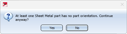
If you choose Yes, the drawings will be created anyway, if you choose No, the drawing creation will be cancelled.
This parameter also has an effect on the Drawing Management.
Itemisation - Automatic conversion of the "old" itemisation with default favourites
The conversion of previous itemisation of drawings (before HiCAD 2018) to the HiCAD standard itemisation can now also be performed automatically, i.e. without displaying the itemisation dialogue. For this purpose, the checkbox When switching to the itemisation mode 'Standard', use the stored default settings is available in the Configuration Editor under System settings > Itemisation > Migration.
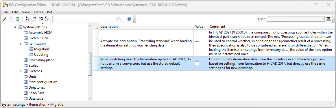
If the checkbox is inactive, then the dialogue of itemisation with options will be started, as before.
If the checkbox is active, then the conversion will be started directly - without displaying the dialogue of the standard itemisation. The Favourites file selected in the Configuration Editor under System settings > Itemisation > Updating will be used.
Major Release 2023 (V 2800)
Units of measurement
Drawing - Free choice of unit of length
The previous version HiCAD 2022 only supported drawings with the unit of length millimetre. As of HiCAD 2023, the unit of length can be selected under System settings > Units > Unit of length in the Configuration Editor. This means that designing in non-metric units is now also possible.
Please note the following:
The settings selected under System settings > Units only apply to newly created drawings. These settings cannot be changed in the drawing itself.
Please note:
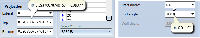
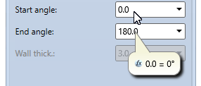
All values inputs in HiCAD are evaluated in the currently set units of measurement. It is also possible to use mixed units. For example, if you have set mm as the unit of length of the drawing and used 1 3/4" + 12.5 mm as the value in a function, the value will be converted to mm, i.e. the result will be 56.95 (mm). If you point to an input field in the dialogues with your cursor, the system will show in which unit the respective value is, e.g.:
In the value inputs where no formulas, fractions, variables, units and spaces are supported, e.g. in the Part attributes dialogue, such inputs will be rejected with an error message, e.g.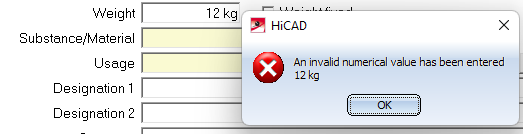
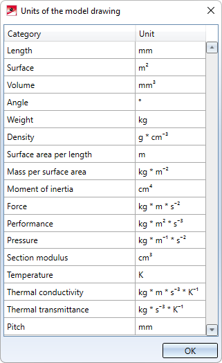
Units of the model drawing
New in the Help Topics and Information is the Units of the model drawing function, which can be used to display the current settings for units, e.g. length, surface, volume etc.
Selecting the region in the parameter configuration
Both during installation and during subsequent parameter configuration with the ParKonfigComp.exe tool, you can now select the region.
|
If you activate North America as the region, the system will automatically switch to imperial, i.e. non-metric units. This applies to:
This means that settings made in the Configuration Editor may be replaced if necessary! This applies analogously to the region Europe. Here, a conversion to metric units, dimensions and scales takes place. |
Constraints in drawings with a unit of length different from mm
If you have selected a unit other than millimetre mm as the unit of length of the drawing, individual functions will not be available. These functions will be greyed out in the ribbons and menus and a corresponding message will be displayed in the tooltip.
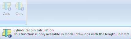
This applies, for example, to the functions
-
Information > 3-D, Further > Cylindrical pin calculation,
-
Information > 3-D, Further > Radial pin calculation,
-
Steel Engineering > Plate, new > Rectangular plate,
-
Steel Engineering > New > Insert series, via DB document master,
-
Steel Engineering > New > Insert series, via DB article master,
-
Metal Engineering > Others > 2-D section of 3-D facade,
-
Metal Engineering > Metal Engineering, 2-D > Sealant/Foil,
-
Metal Engineering > Metal Engineering, 2-D > Sheet,
-
Metal Engineering > LogiKal, 2-D > Insert facade + inserts from existing LogiKal project,
-
Metal Engineering > Interfaces > Create WinIso2D part,
-
Metal Engineering > Interfaces > Export to eluCad,
-
Sheet Metal > New > Pipes + Vessels
as well as individual Plant Engineering and P+ID functions.
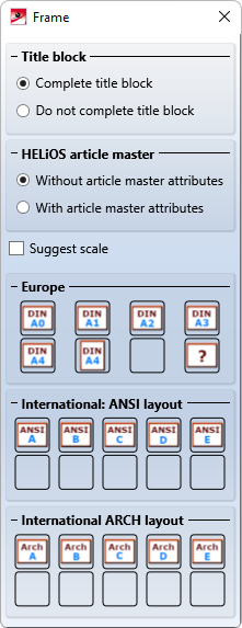
Drawing frame for North America
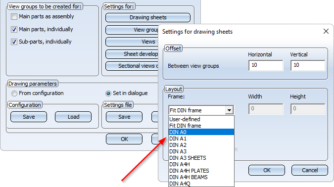
If North America is selected as the region during installation or during subsequent parameter configuration, additional drawing frames are available in the Insert drawing frame  function.
Formulas, mixed numbers and units when entering points
In the numerical point options, you can enter the numerical values required for the point option in one step, e.g. relative coordinates. Formulas and mixed numbers are now also permitted, e. g. (a+b), 1/2, 1 3/4" + 12.5 mm. In this case, you must note the setting in the Configuration Editor under System settings > Miscellaneous > Pocket calculator.
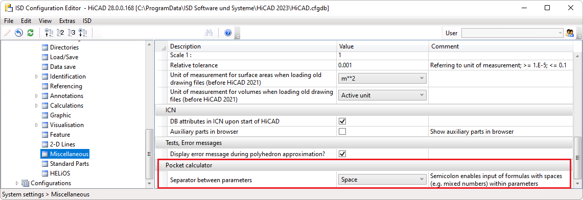
- Space
With this setting, the different entries must be separated by spaces. If formulas, mixed numbers or mixed units are used, they must not contain spaces. This is the ISD default setting. - Semicolon
If you want to use formulas etc. with spaces, you must select this setting. The different entries must then be separated by semicolons.
Example:
You want to use the coordinates X=(a+b)/2 y=70, z= 90 for the point option R, where a and b are part variables with the values a=50 and b=7.
|
Setting |
Entry |
Result |
|
|---|---|---|---|
|
Space |
R (a+b)/2 70 90 |
28.5 70 90 |
correct |
|
Space |
R (a + b)/2 70 90 |
Returns 0 as X value and queries the other coordinates |
false |
|
Semicolon |
R (a + b)/2;70;90 |
28.5 70 90 |
correct |
Mark-up and Redlining
The HiRedLine tool allows you to add comments or modification suggestions to a HiCAD drawing, without changing the original file.
As of 2023, this tool is only available as part of a HiCAD/HELiOS installation. In case of a standalone installation of the HELiOS Desktop, starting it will no longer be possible.
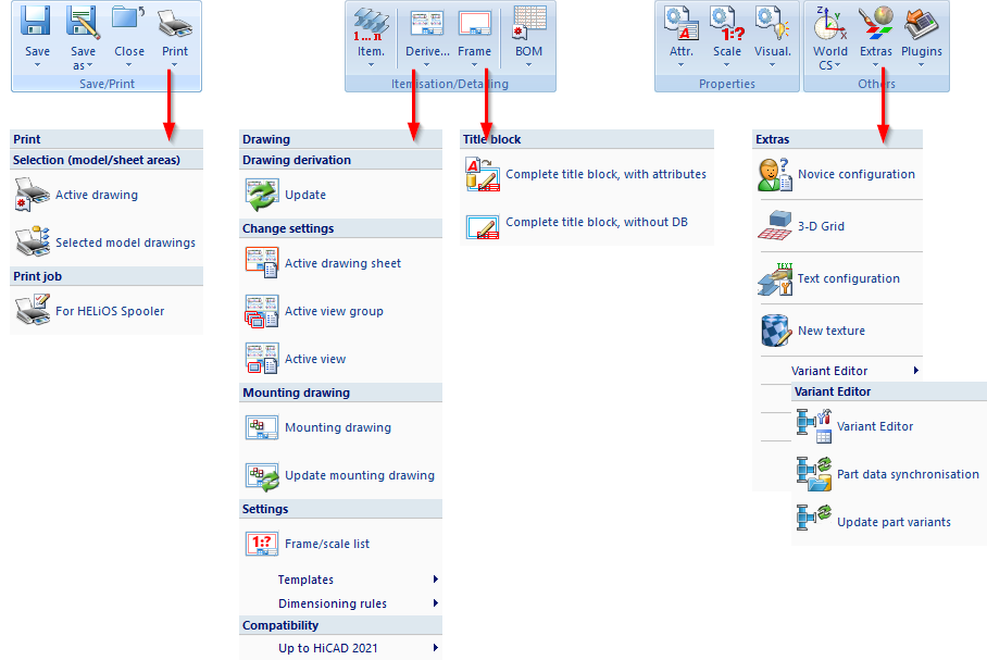
Ribbon adjustments
The Drawing, Views and Sketch ribbons have been slightly modified and tightened. The most important adjustments at a glance:
Drawing
- The print functions have been combined in a pull-down menu.
- You can now send drawings via e-mail under Save as.
- The Variant Editor has been moved to the Extras menu.
- You can find the functions for the creation and updating of mounting drawings as well as the templates and dimensioning rules/settings for the drawing derivation in the pull-down menu of the drawing derivation.
- The insertion of drawing frames has been moved to the Itemisation/Detailing area. You can complete the title blocks using the functions of the pull-down menu.
- Showing/hiding by element type has been moved to the Properties area.
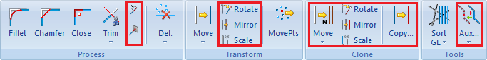
Sketch
- You can close internal corners and lengthen/shorten lines directly via the Sketch ribbon.
- You can directly access the functions for setting/deleting auxiliary geometry from the Sketch ribbon.
- The functions under Transform/Clone have been arranged differently.
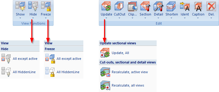
Views
- The functions for hiding and freezing have been each combined in a pull-down menu.
- The functions for updating cut-outs, sectional views and detail views have been combined in a pull-down menu.
User libraries
As of 2023, the functions for part and macro libraries are no longer available in the Drawing ribbon during a new installation. Existing customers who wish to continue using their existing libraries can switch on the functionality in the Configuration Editor under Compatibility > User library up to HiCAD 2022 by activating the corresponding checkbox.
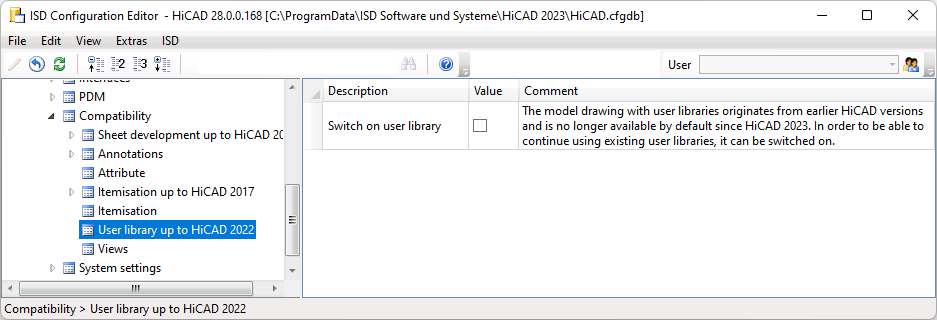
When updating from a version prior to HiCAD 2023, the user library is still switched on for existing customers. In the case of an update from HiCAD 2023, the current setting from the Configuration Editor will be adopted.
Moving the screen display
The screen display can now also be moved by holding down the right mouse button and dragging the display to the desired position. This corresponds to the behaviour of the CTRL + middle mouse button combination. If the right mouse button is simply pressed, the 3-D view context menu will be called instead.
Derived drawings
Annotation of identical bores
You can use the Dimension Settings  function to combine individual bores which do not belong to a bore pattern on the Annotations tab by activating the Specify number of bores checkbox. The annotation will then occur only once with specification of the number.
If only one annotation is to be set for all identical bores - regardless of whether they are individual bores or bore patterns- this can be set via the Annotate each hole diameter only once checkbox.
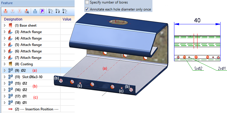
Left: Model with (a) bore pattern 3 x Ø2 as well as (b) two individual bores Ø2 and (c) two individual bores Ø1
Right: Detail of the workshop drawing
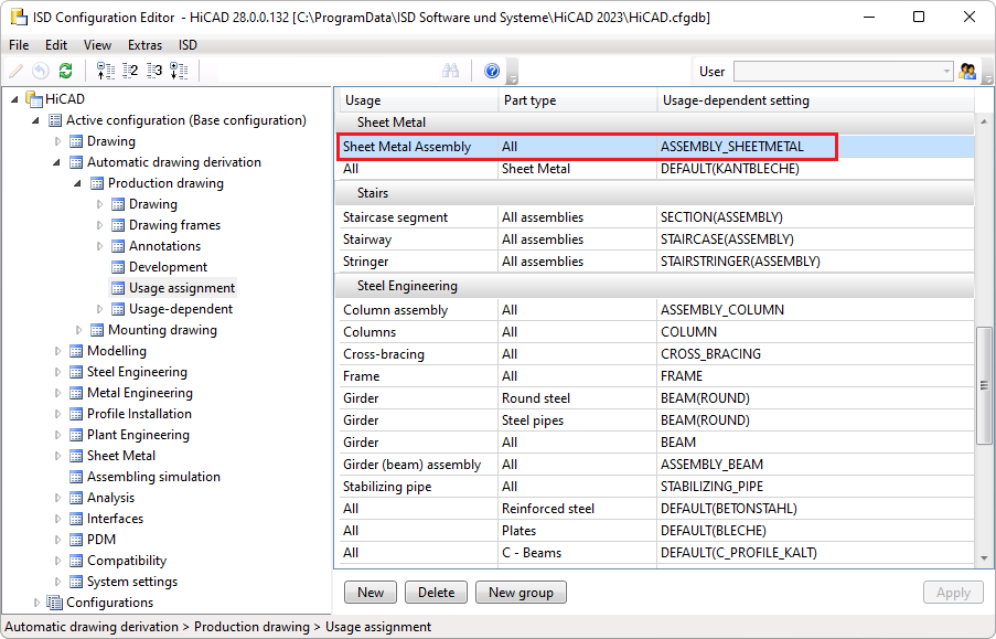
New usage for sheet metal assemblies
A new usage is available for sheet metal assemblies, i.e. assemblies with a sheet as the main part: Sheet Metal Assembly. For this purpose, the Factory standards > Usage catalogue has been extended accordingly.
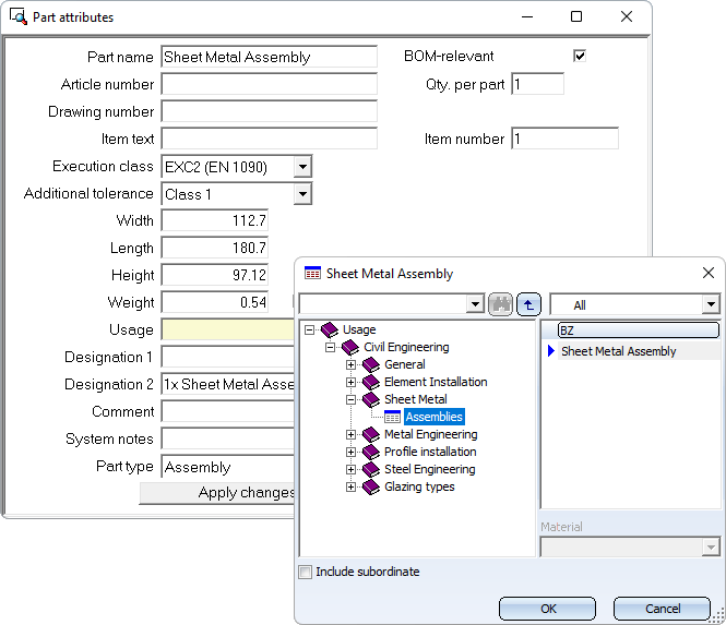
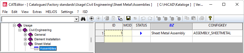
For assemblies with this usage, usage-dependent configurations can be used for drawing derivation, which are managed in the ISD Configuration Editor, as for other usages. By default, the configuration ASSEMBLY_SHEETMETAL is predefined for assemblies with the usage Sheet Metal Assembly.
Production and mounting drawings - Drawing frames
As of HiCAD 2023, two additional parameters are available for production drawings in the Configuration Editor under Automatic drawing derivation > Production drawing > Drawing frames.
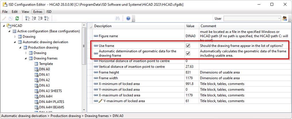
Use frame
This checkbox determines whether the frame should be offered for selection in the Drawing derivation dialogue or not. The ISD default setting is yes, i.e. the checkbox is active.
Detail of the Drawing derivation dialogue
Automatic determination of geometric data for the drawing frame
For each drawing frame,
- the distance of the insertion point from the centre of the frame,
- the size of the usable area (frame height / frame width) and
- the size of a blocked frame area (for the title block, BOMs or comments)
can be defined. If the blocked area is specified incorrectly or is missing, the automatic drawing derivation may cause views to collide with the title block.
If the blocked area of a frame is to be determined automatically during drawing derivation - including the width and height of the usable area - this can now be achieved by activating the Automatic determination of geometric data for the drawing frame checkbox. This is the ISD default setting for the drawing frames included in the delivery. If the checkbox is active, only the figure name can be specified if required. All other settings can be omitted.
|
|
Analogously, the parameters listed above are also available for mounting drawings under Automatic drawing derivation > Mounting drawing > Drawing frames.
Using frame/scale lists
During drawing derivation, there is often a desire to display everything on one sheet if possible. Sometimes it is also desired that sectional views, developments or axonometries should have different scales than the main view. Additionally, there are situations where the customer wants a certain drawing frame to be filled with views at an optimal scale. For example, a drawing frame DIN A2 should be used and the scale of the views should be adjusted accordingly. However, if the scale falls below 1:10, another drawing frame should be used.
This cannot be configured in the options of the drawing derivation. Here the new function  Frame/scale list is the ideal solution.
Similarly to the dimensioning rules, this function can be used to define separately for each purpose, for example for assemblies, I-beams, sheets, etc., which drawing frames combines with which scales should be used. This also significantly increases performance when creating drawings, as HiCAD does not have to search through all drawing frames and scales.
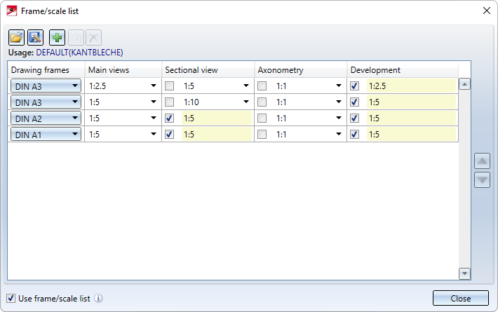
Example of a frame/scale list for sheet metal parts
But what is the effect of the example shown above?
If the list is activated, then during drawing derivation, instead of the other settings for frame sizes and scales the list entries will be checked in sequence until a drawing fits on a sheet.
Thus, in our example, the following is checked for the detail drawings of sheets:
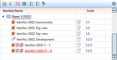
- Does the drawing fit into the DIN A3 frame if main views and developments are shown at a scale of 1:2.5, axonometries at a scale of 1:1 and sectional views at a scale of 1:5? If yes, the drawing will be created and not checked further. The figure shows an example of the corresponding view structure.
If no, step 2 will be executed.
- Does the drawing fit into the DIN A3 frame if main views and developments are shown at a scale of 1:5, axonometries at a scale of 1:1 and sectional views at a scale of 1:10? If yes, the drawing will be created and not checked further. If no, step 3 will be executed.
etc.
If the drawing does not fit any of the frames, a corresponding message will be displayed:
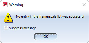
|
|
You can find a detailed description of the function here.
New system attributes
In HiCAD, new system attributes are available for sheet metal parts and coated surfaces:
|
Attribute name |
Attribute description |
Type |
|---|---|---|
|
§CW |
Weight from rectangular surface of development |
DOUBLE |
|
§S2D |
Rectangular surface of development |
DOUBLE |
|
§SC |
Coated surface |
DOUBLE |
|
§SOC |
Surface from development contour |
DOUBLE |
New docking window for variables
The docking window for variables docking window for variables has been completely revised for HiCAD 2023. In contrast to the old variable window, the entries no longer have to be saved or discarded using OK or Cancel. Instead, you can activate or deactivate the automatic feature recalculation. If it is activated, a recalculation takes place after every action in the variable window. An exception is the change of the comment.
For more information, see the Feature Technology News.
