3-D Coordinate Systems
World CS
Drawing > Others > World CS > World CS
The world coordinate system (abbreviated as world CS) provides the reference for the drawing and cannotbe changed. Its planes represent the main planes, i.e. front view, side view and top view of the drawing.
When creating a new drawing, firstly the world CS is defined only and thus the active coordinate system.
In 3-D its reference point lies in the point (0,0,0).

Part CS
Drawing > Others > World CS  > Activate 3-D Part CS
The Part Coordinate System (short: Part CS) describes the position of a part in an assembly. At the same time it is a reference for the contents of the part itself. All coordinates of the part are stored by HiCAD relative to this coordinate system.
For example, if you place an isolated point at the local zero point of the part CS, that point has the coordinates (0,0,0) in the feature log. This also applies if other coordinates that are referred to another CS were entered during setting.
Part coordinate systems cannotbe changed.
Referencing
Modifications of referenced parts are transferred to all locations where the part is used. The position of the part is not changed.
Use the Activate 3-D Part CSfunction to activate it.
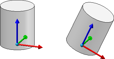
Left: Parts CS of a cylinder during creation, Right: Parts CS after rotating the cylinder
![]() Please note:
Please note:
- Assemblies also have a part coordinate system. In contrast to simple parts, this coordinate system can either be determined automatically by HiCAD or defined when creating a new assembly as well as when editing the assembly structure. A respective parameter is available under Modelling > Part creation > Assembly.
- The symbolic representation of the part coordinate system can be shown/hidden via the visualisation toolbar.
Fitting CS
The Fitting coordinate system (or fitting CS for short) determines the orientation of a part when inserted into a drawing. It is also used as a reference when exchanging parts.
The fitting CS is set automatically when referencing a part, but can also be changed subsequently with the function and also parameterized via the feature protocol. Fitting coordinate systems are particularly required whenever customer-specific installation elements or railing components are required. Here, the installation coordinate system ensures that these objects are placed correctly.
Use the
 Define Fitting CSfunction to specify a Fitting coordinate system.
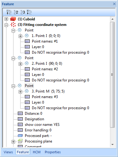
The Fitting CS consists of 3 special points, to which point designations from #1 to #3 are assigned:
- the origin of the Fitting CS (#1)
- a point on the x-axis of the fitting coordinate system (#2)
- a point in the (x,+y) half-plane of the fitting coordinate system. (#3)
If a 3-D part to which a Fitting CS has been assigned is loaded into a new drawing, the points of the fitting coordinate system are placed in the world coordinate system. This defines the fitting direction in space. The exact position in space is defined, as usual, through specification of a fitting point pair.
 Please note:
The Fitting coordinate system will be entered as a same-named feature step into the Feature log. There you can assign an additional designation to the Fitting CS which will then be shown both in the feature log and in the drawing.
An example:
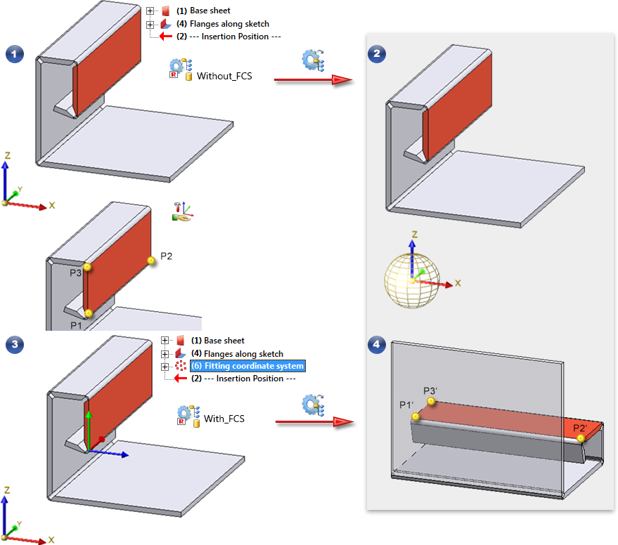
The following figure shows a sheet. In the first step, this sheet without fitting CS has been saved with the function Drawing > Reference > Part.. , for instance with the name Without_FCS. This part was then built into a new drawing using the Explorer (2). Then a fitting CS was defined for the sheet metal in the original model drawing (3) by determining the points P1, P2 and P3 (left lower / right lower / left upper corner of the red surface). Then the sheet was saved again, for example With_FCS. This sheet metal was then also built into the new construction (4). You can clearly see that the fitting direction has changed. P1', P2' and P3' are the fitting CS points transferred to the World CS.
 Important:
- Please consider the notes on the insertion of a fitting CS with referenced 3-D parts.
- A part can have only one fitting coordinate system. If you have defined several fitting coordinate systems in succession, the last defined fitting coordinate system will be used and saved to the base data. This rule also applies if several entries for fitting coordinate systems exist in the feature log of the corresponding part.
This behaviour also applies for legacy data from older HiCAD Versions (before 2002.2)! - If a fitting coordinate system has been defined for a part several times, and the Delete Fitting CS...
 function is then applied to this part, the previously defined fitting coordinate systems will still be shown in the feature log. After a recalculation, the last but one fitting coordinate system will apply.
 - If the base data of a part (from HiCAD versions before 2100.0) contains several fitting coordinate systems, the last defined fitting coordinate system will apply here, too.
- The symbolic representation of the part coordinate system can be shown/hidden via the visualisation toolbar.
In order to delete a Fitting CS, use either the Delete Fitting CS, Active part
or  Delete Fitting CS, Active part and sub-partsfunctions.
Assembly CS
Drawing > Others > World CS > Change assembly coordinate system 
Like every part, an assembly also has a part coordinate system. This coordinate system is either determined automatically by HiCAD or defined by you when creating the assembly. For this purpose, a corresponding parameter is available in the Configuration Editor at Modelling > Part creation > Assembly.
With this function you can change the assembly coordinate system if required.
![]() Important:
Important:
Note that this can also change the geometry and position of the parts in your drawing. Referenced parts will change at all points of use.
Example from Feature with external reference:
The isolated point set with the point option K refers to the part coordinate system of the assembly. If you change the coordinate system, the position of the point and all elements that refer to the point also change.
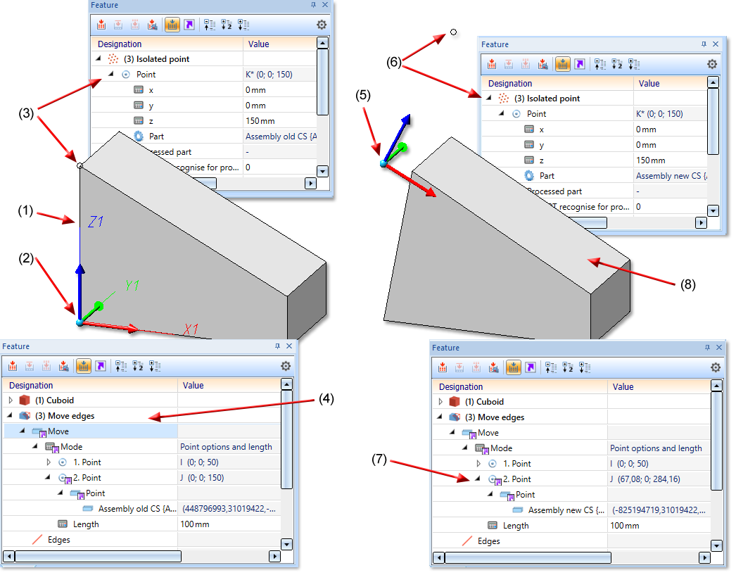
(1) Part of Assembly, (2) Coordinate system of Assembly, (3) isolated point refers to the Assembly CS, (4) Feature Move edges with external reference to Isolated point
(5) Assembly CS changed, (6) as a result, the position of the Isolated point changes, (7) Feature Move edges with external reference to Isolated point, (8) Geometry is adjusted accordingly
Beispiel aus HCM:
Coincidence (3-D Part HCM) exists between a plane of the cuboid and the XY-plane of the part coordinate system of the assembly. If you change the position of the coordinate system, the position of the cuboid will also be adjusted.
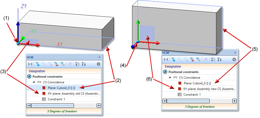
(1) Coordinate system of the assembly, (2) first plane for the coincidence is the lower surface of the cuboid, (3) second plane of the coincidence is the XY-plane of the coordinate system
(4) assembly coordinate system changed, (5) (6) coincidence rotates the plane of the cuboid back to the XY-plane of the coordinate system
Processing Plane
Drawing > Others > World CS
A processing plane is a coordinate system represented as a plane. A processing plane can be manually specified, changed or deleted at any time.
To define a processing plane, activate
 Processing Plane
To specify the processing plane, you can identify points, edges, surfaces and also processing planes of the drawing in any order.
Further functions for defining the processing plane are provided by pressing the right mouse button instead of an identification.
More information on Processing planes can be found here.
Active / Local Coordinate System
In HiCAD, there is exactly one active coordinate system referred to when entering and displaying coordinates. This can be the world coordinate system, a part coordinate system or a working plane.
When creating a new drawing, the world coordinate system is always active; when loading a drawing, it is always the coordinate system that was active when the file was last saved!
To activate the coordinate system, use the functions under Drawing > Others > World CS
In general, the active coordinate system is a copy of the initial coordinate system and is called a local coordinate system. This can be changed to use a different reference at short notice. In this case the active coordinate system does not conform to any of the coordinate systems that can be activated. However, this only applies temporarily unless another coordinate system is activated.