Feature Technology - What's New?

Service Pack 2 2023 (V 2802)
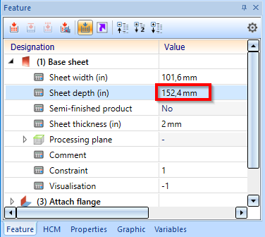
Indication of deviating units
If a part is inserted into a drawing created with a different unit, this will be indicated in the feature ICN by displaying the original unit.
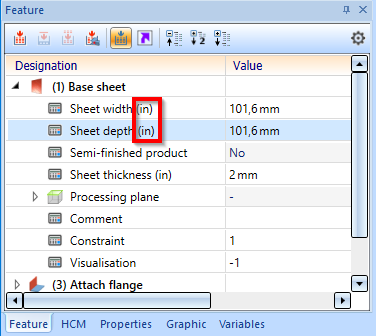
A Sheet Metal part created in an inch drawing is inserted into a millimetre drawing.
The change of values is done with the pocket calculator in the original unit.
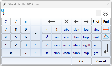
The depth of the sheet is changed from 4 to 6.
If, for example, you change the feature of a cone in the creation dialogue, the original unit will also be displayed here.
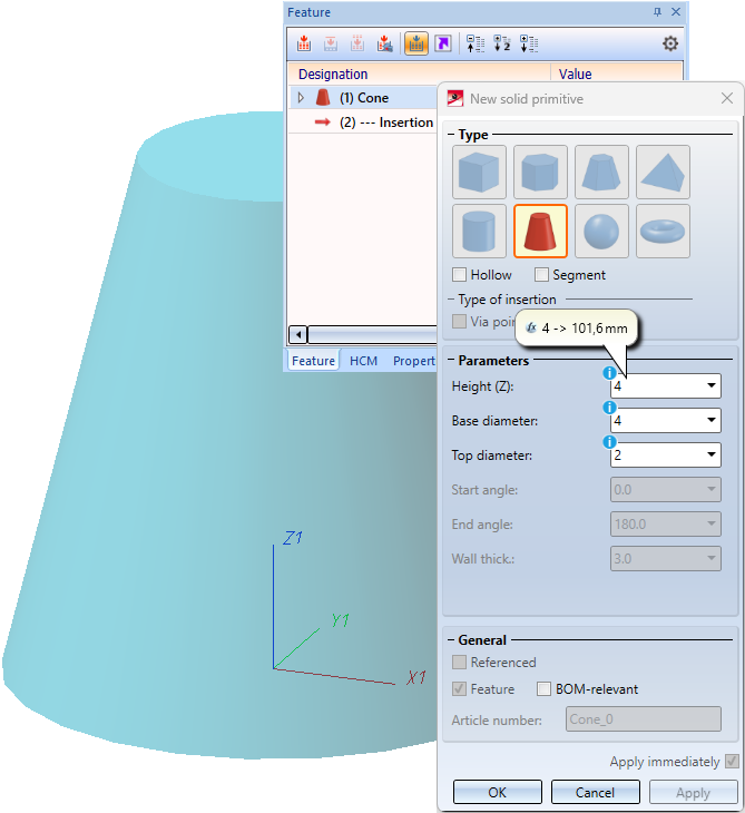
In dialogues, input fields containing deviating units are indicated with a blue info icon.
Change assembly coordinate system
Like every part, an assembly also has a part coordinate system. Until now, this coordinate system could either be determined automatically by HiCAD or set by you when creating the assembly. For this purpose, a corresponding parameter is available in the Configuration Editor at Modelling > Part creation > Assembly.
From HiCAD 2023 SP2 onwards you can also move the part coordinate system of assemblies with the new function Change assembly coordinate system  (Drawing > Others > World CS
  > ...).
![]() Important:
Important:
Note that this may also change the geometry and position of the parts in the drawing. Referenced parts will change at all points of use.
Example of a feature with external reference:
The isolated point set with the point option K refers to the part coordinate system of the assembly. If you change the coordinate system, the position of the point and all elements that refer to the point will also change.
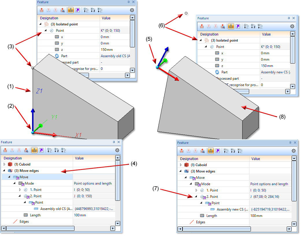
(1) Part of Assembly, (2) Coordinate system of Assembly, (3) isolated point refers to the Assembly CS, (4) Feature Move edges with external reference to Isolated point
(5) Assembly CS changed, (6) as a result, the position of the Isolated point changes, (7) Feature Move edges with external reference to Isolated point, (8) Geometry is adjusted accordingly
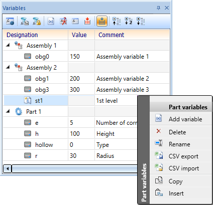
Selection of already created variables
From HiCAD SP2 onwards, the part variables that you have already created for the assembly will also be displayed when choosing the Edit formula function. One character is sufficient for auto-completion.
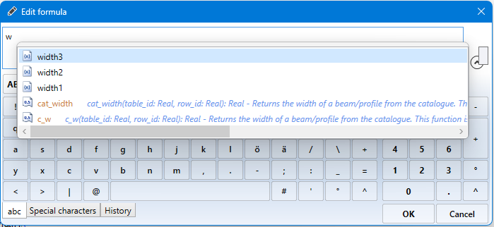
To display all formulas and variables, place the cursor in the input field and enter the key combination CTRL + Space bar.
Automatic recalculation after changes
If the Automatic recalculation is deactivated(off) in the toolbar of the feature window (ICN), from HiCAD 2023 SP2 onwards the automatic feature recalculation in the variable window (ICN) is no longer deactivated as well. The calculation can now be carried out independently of each other.
(1) Automatic recalculation off
(2) Automatic feature recalculation on
Service Pack 1 2023 (V 2801)
Sketch feature - Element snap mode
The user guidance for the Process sketch feature has been changed.
Previously, in Element snap mode, holding down the SHIFT key while clicking the right mouse button (1) on a sketch element highlighted the sketch and geometry in colour (2). This made the selection of sketch elements difficult in many cases. In addition, when editing the sketch, for example, HCM constraints could be set that referred to elements that did not actually exist, which could lead to feature or HCM errors. The following figure shows such an example. Here, when changing the sketch of a recess, an HCM dimension (3) was set from the subtraction contour to the sketch.
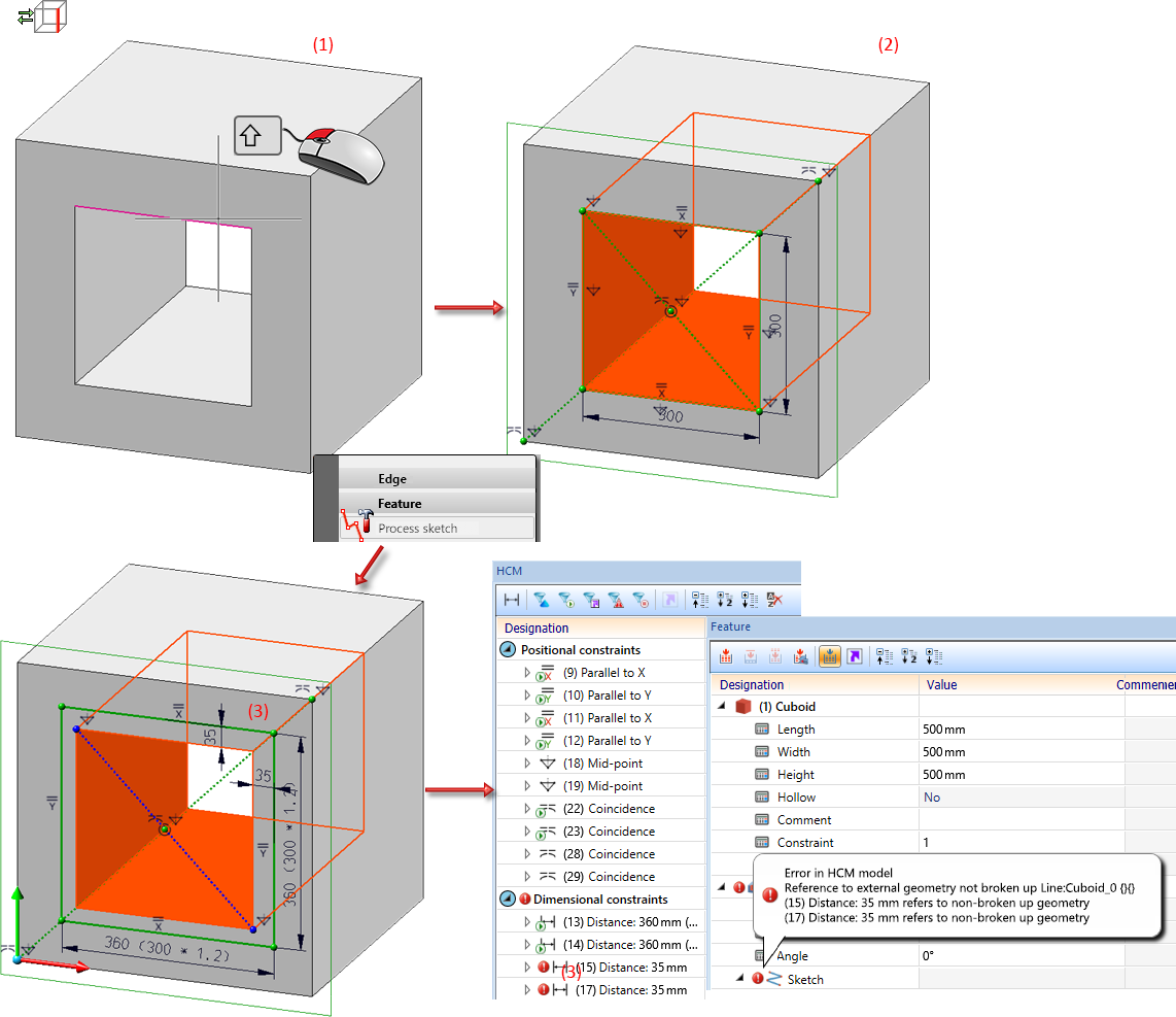
As of HiCAD 2023 SP1, the user guidance changes as follows: If a sketch element is selected in the drawing with SHIFT+ right mouse button in the Element snap mode and then the Process sketch function is called up in the context menu for edges, then only the sketch is highlighted in colour and calculated to the initial position. This avoids feature and HCM errors - as shown above - and simplifies the selection of sketch elements. This behaviour also applies when double-clicking on the Sketch entry in the feature as well as for all cases with which a Sketch feature can be edited.
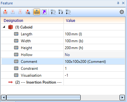
Parameterization of string variables via formulas
Up to now, only variables of type Number in the variable table could be controlled via a formula. As of HiCAD 2023 SP1, String variables can also be parameterized.
To insert a string variable into a comment, for example, proceed as follows:
Create the Number Variables l, b und h for the Length, Width and Height of a cuboid (1). Then create the String Variable Comment (2). Enter the formula for the new variable using the Edit formula function from the context menu (3).
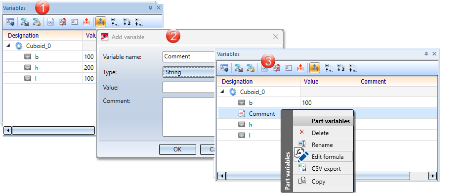
Enter the formula real_to_string(l) + 'x' + real_to_string(b) + 'x' + real_to_string(h).
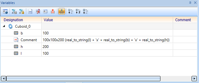
Comments or the Designation of parts can now be parameterized in the Feature.
![]() Please note:
Please note:
All formulas that are not used for a numerical value can only be entered using the Edit formula function in the context menu. This also applies to string variables. A direct input when creating the string variables with the Value option is not evaluated.
Major Release 2023 (V 2800)
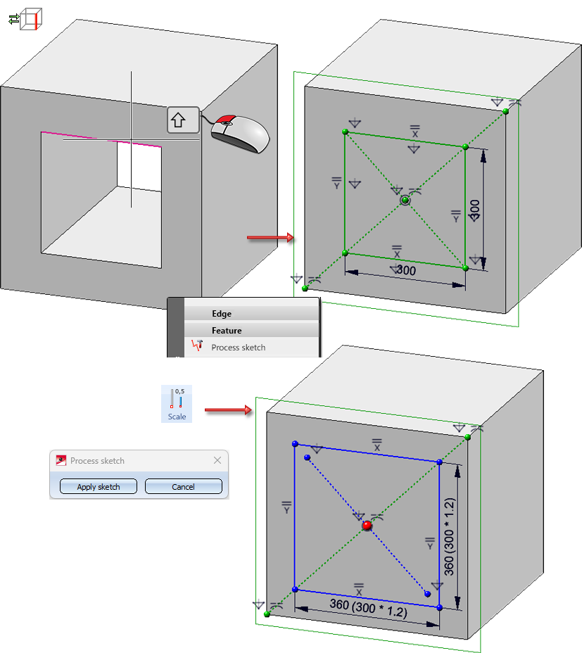
Edit feature - Element snap mode
If the identification mode Element snap  is active, then clicking with the left mouse button on a geometry will mark the associated feature in the ICN. Double-clicking this feature opens the corresponding processing dialogue:
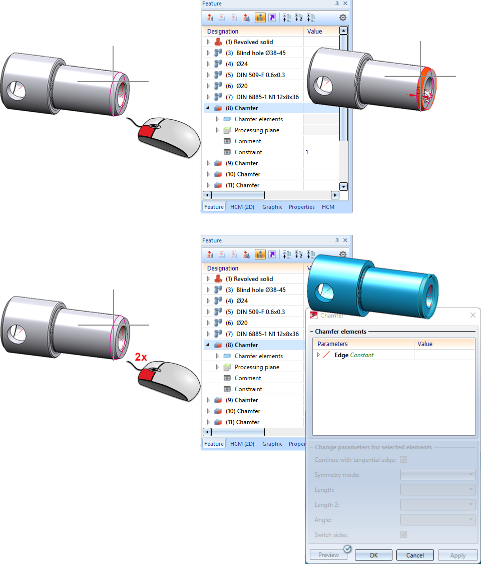
You activate the Element snap mode on the transparent toolbar:

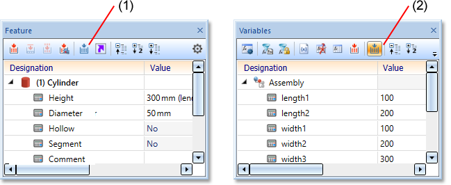
New docking window for variables
The docking window for variables has been completely revised for HiCAD 2023. In contrast to the old variable window, the entries no longer have to be saved or discarded using OK or Cancel. Instead, you can activate or deactivate the Automatic feature recalculation . If it is activated, a recalculation takes place after every action in the variable window. An exception is the change of the comment.
|
|
With this function you switch between part variables and view variables. If the Automatic feature recalculation View variables at Drawing > Properties > Attr... could be removed. |
|
|
|
Activate/deactivate variables of active feature log |
This filter restricts the view to all variables used in the feature log of the active part. |
|
|
Activate/deactivate variables of active HCM model |
This filter restricts the view to the variables used in the active HCM model. |
|
|
With this function you activate the dialogue for adding variables. The variables are added to the active part or view variables. |
|
|
|
All unused variables are marked. The user can delete the marked variables afterwards via the context menu. |
|
|
|
This function opens the Use of variables dialogue window, which lists for all variables of the selected part where (and whether) they are used in other places in the drawing. |
|
|
|
With this function you start the feature recalculation of the active part or the recalculation of all views. |
|
|
|
You can switch the automatic feature recalculation or the recalculation of all views on or off with this function. |


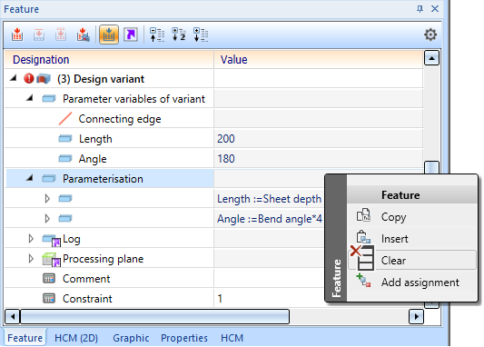
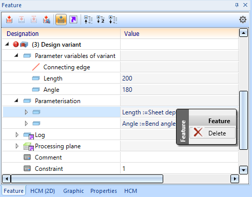
Delete and Clear assignments under Parameterisation
Two functions are now available for deleting the parameterisation of a Design Variant:
- Right-click on the main entry Parameterisation and select Clear. All parameterizations of the Design Variant will then be deleted.
- Right-click a parameterisation in the sub-menu and select Delete: Then only this parameterization will be removed.