![]()
![]()
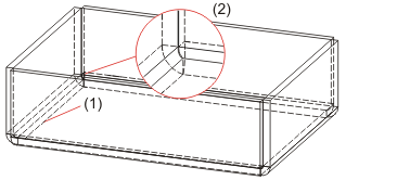
The revised sheet creation function New sheet along sketch allows a processing of sketches while the dialogue window is open.
As soon as you have identified the sketch a preview of the new sheet will be displayed. To change the sketch, click on the  Process sketch icon. The Sketch tab and the Process sketch dialogue will then be displayed. Change the sketch and confirm with Apply sketch. The Sheet along sketch dialogue will then be displayed again.
You can expand the Bend zones area by clicking the  icon, and enter an individual radius and allowance for each band zone.
The Offset direction and the Fitting direction each offer 3 options than can be selected (complete with visualization) from a pull-down menu.
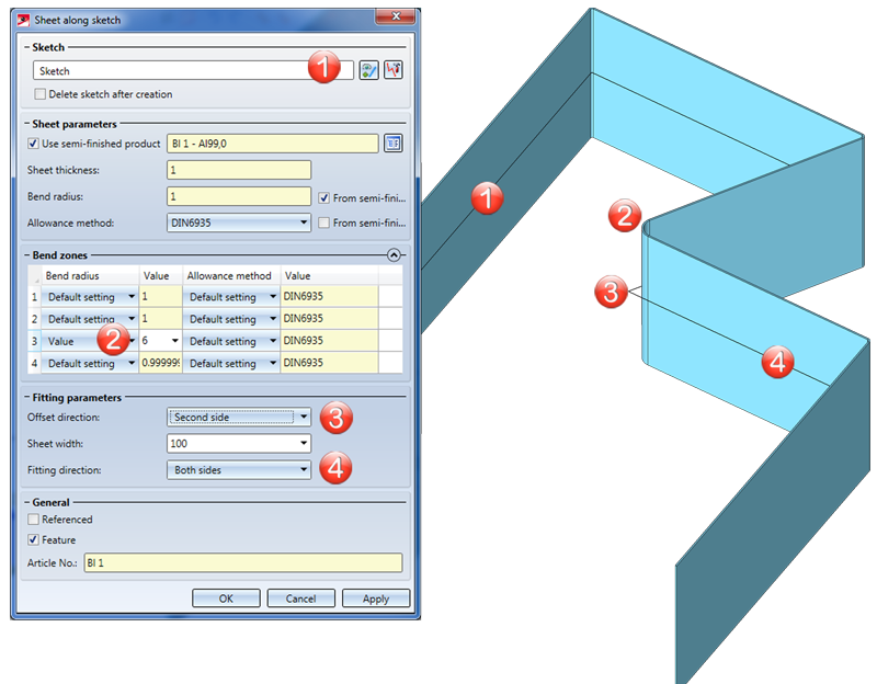
(1) Sketch
(2) Bend radius changed
(3) Sheet thickness
(4) Fitting direction

![]()
HiCAD now offers the new Sheet Metal cassette Design Variant for the construction of high-level functionality facades with a striking appearance. This Design Variant allows you to create rectangular or polygonal cassettes using Sketch technology.
The dialogue window consists of two tabs:
On the Base sheet tab you determine the corner points of the contour. You can either enter the coordinates,or identify the points in the drawing, or select a sketch. Use the options beneath Close corner to to mitre attached flanges (or sheets and bend zones, respectively) in one step. In the process, the bend zone will either be trimmed, adjusted or, if you choose Mitre (indiv.) with lengthening ignored.
On the Attach flange you can then define the attached flanges. You can assign a different flange to each edge of the base sheet. You can use most parameters of the Sheet Metal function Attach flanges here.
Click Preview to check and, if required, modify the result. Later changes can be applied via the feature log.
![]()
Libraries for Bore patterns and Punching tools can be found in the Factory standards catalogue, and a library for Moulding tools can be found in the Sheet tools catalogue of the Catalogue Editor. An expanding of these libraries was previously only possible with 2-D parts that could be parameterized with the 2-D HCM (file format: .DCF). Now, it is also possible to store planar sketches that can be parameterized with the Sketch HCM (file format: .KRA).
![]()
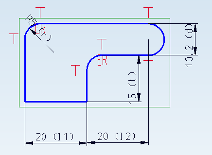
The Bore patterns library now also contains Agrafes. These can be used, e.g., for the anchoring of plates in facade constructions; they are not visible from the outside.
Parameters in the catalogue:
l1 = 20
l2 = 20
d = 10,2
r = 5
t = 15
Insertion point: Centre of right semi-circle
The image below shows an agrafe for the left side. The right side can be selected via the Orientation.
![]()
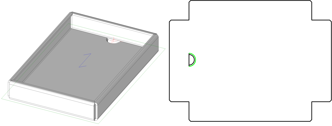
Three new functions for the export of section contours are available. These functions export the contours of the blanks of Sheet Metal parts and Steel Engineering plates as DXF files. A prerequisite for this is that they are:
Blanks in the drawing will be ignored. HiCAD will always output a blank that is created temporarily for the export. The current pre-settings in the drawing will be used for blank generation. The alignment is only unambiguous when it has been specified with the Processing direction function.
The 3 available functions support you with the selection of the sheets or plates:
All sheets: The developments of all sheet main parts in the drawing will be exported.
Sheets from list: All marked sheets and plates (part selection list) will be exported as a DXF file. The "quantity" of the parts per item number will be taken from the drawing - irrespective of the selected and displayed parts.
Active sheet: Only the active sheet main part will be exported.
Proceed as follows:
A dialogue window with a list of the DXF files to be exported will be displayed
The files will then be located in the previously selected directory.
![]()
The behaviour during DXF export of Sheet Metal part and Steel Engineering plate blanks has changed.
This affects the following functions:
 > DXF: Complete - All sheets > DXF: Complete - Sheets from list > DXF: Complete - Active sheet
 Use these functions to export the blanks of Sheet Metal parts and Steel Engineering plates as DXF files. A prerequisite for this is that they are:
As of SP2, blanks in the drawing will be ignored. HiCAD will always output a blank that is created temporarily for the export. The current pre-settings in the drawing will be used for blank generation. The alignment is only unambiguous when it has been specified with the Processing direction function.
![]()
When outputting a temporarily created blank for the export, a list of DXF files is shown. This list can now be saved as a CSV file.
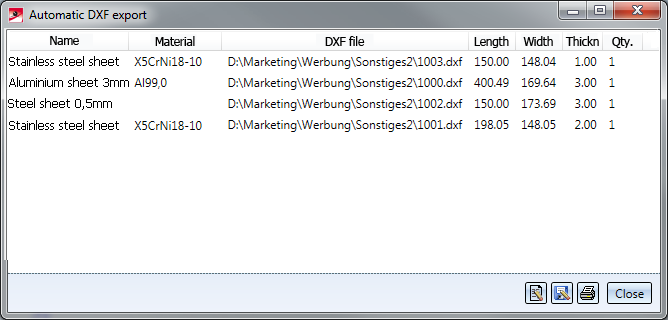
Click the  icon to save the list as NAME.TXT or NAME.CSV to the selected directory.
In the file ABWPAR.DAT you can specify the output mode (Standard or Extended) (Default or Expanded) and the output format (TXT file or CSV file). The settings will only take effect after a restart of HiCAD.
![]()
The calculation time required for the cleaning up of intersections could be reduced significantly. In test examples, time savings from 30% to 50% could be observed.
![]()
You have now the option to individually specify bend lined in blanks with the settings of the file ABWCOL_BEND_ANGLE.DAT. Whether this file will be evaluated depends on the corresponding setting in the file ABWCOL.DAT.
Set the following parameter in the file ABWCOL.DAT to 1 and restart HiCAD:
Biegelinienfarbe soll in Abhängigkeit vom Biegewinkel gesetzt werden; Datei "sys/abwcol_bend_angle.dat" (1: Eigenschaften aus Datei lesen; 0: nicht aus Datei)
1
Then, change the settings in the file ABWCOL_BEND_ANGLE.DAT. Simply save the file to apply the changes after updating of the blank.
Positive and negative bend angles are distinguished the file ABWCOL_BEND_ANGLE.DAT. Only the data within the BEGIN-END block may be changed.
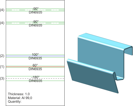
(1) Bend angle 0°- 95°, Line code (Layer, Colour, Weight, Type) 2411
(2) Bend angle 95°- 360°, Line code (Layer, Colour, Weight, Type) 2311
(3) Bend angle -360°- -95°, Line code (Layer, Colour, Weight, Type) 2013
(4) Bend angle -95°- 0°, Line code (Layer, Colour, Weight, Type) 2117
![]()
Lantek Flex3d is a software solution for the automation of sheet metal cutting machine programming.
The interface between HiCAD and Lantek Flex3d is created via the export of the blank as DXF file.
To ensure a smooth data exchange, the blank needs to be composed according to Lantek-specific requirements.
 to view the blank parameters.
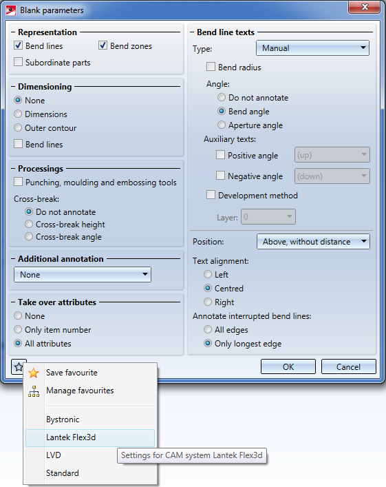
 icon to open the Favourites. Load the parameters for Lantek Flex3d.
  function.
 The format of the abwpar.dat and the abwcol.dat files has changed due to changes of the files in connection with Bend angle-dependent bend line parameters.
![]()
Use the Coating function to define the coating description, the coating colour (RAL colour, system colour) and the coating type (outer side, inner side, edge) of a Sheet Metal main part.
The coating description and the coating type are taken over into the part attributes mask and are then also available in BOMs.
After selecting the outer sheet side you will be shown a preview of the coating, provided that you have not activated any options requiring further value inputs. If you have activated the Apply immediately checkbox, the coating parameters will be applied immediately if the value inputs were correct, enabling you to select the outer sheet side of a new Sheet Metal main part. Changes can then be made via the feature log.
If you want to change a surface after its identification, click the  icon and identify the new surface.
If you are working in the shaded mode, the coating will be shown in the selected colour. You can select a RAL colour from the catalogue or a system colour as the coating colour. Activate and click the  icon to display a selection list with the RAL colours. Otherwise, you can pick a system colour from the Colour selection box.
If you have selected a RAL colour, you can also take the description from the catalogue  .
.
Use the 
 icons to copy, for instance, the parameters of the outer side to the inner side and vice versa.
You can display the front surfaces in the colour of the outer side or inner side, respectively. This setting will be taken over into the part attributes mask.

(1) Surface on the outer side
(2) Outer side
(3) Inner side
(4) Front surface like outer side
![]()
The functions
now offer the option to activate, deactivate of change the semi-finished product by double-clicking the feature.
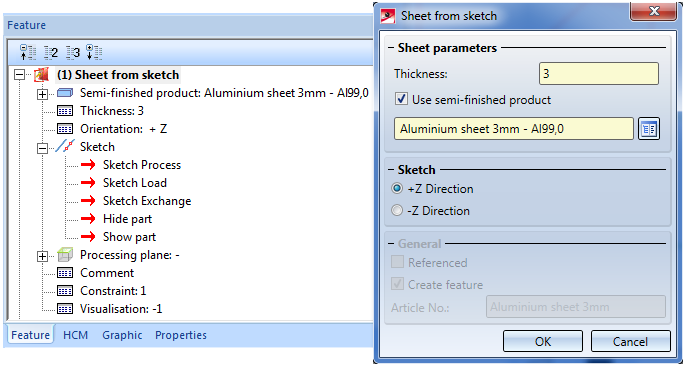
Double-clicking the feature Sheet from sketch opens the same-named dialogue window. You can then activate or deactivate the Use-semi-finished product checkbox, or click  to and a different semi-finished product. Confirm with OK.
![]()
In the Configuration Editor you can specify the semi-finished product attributes that you wish to take over into the a manually created article master. It is important that you created the article master yourself (manually) using the Create new article master + assign function instead of applying a semi-finished products article master through selection of a semi-finished product during base sheet creation.
Also, each catalogue table column to be taken over needs to be linked to a HELiOS attribute. The table will then be transferred to HELiOS.
![]()
When creating sheets with the functions
you have now the option to change the article number, if no semi-finished product has been selected. If the Use-semi-finished product checkbox has been activated, the article number of the sheet will be generated automatically.
Double-clicking the feature opens the dialogue window for sheet creation. Here, too, the article number can only be changed if the Use-semi-finished product checkbox has not been activated.
![]()
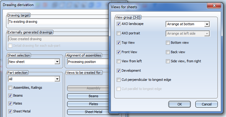
You can now select the following sectional views for Sheet Metal parts in the Views for sheets dialogue window that you open by clicking the Sheet Metal button in the Drawing derivation dialogue window (Drawing > Itemisation/Detailing > Derive):
![]()
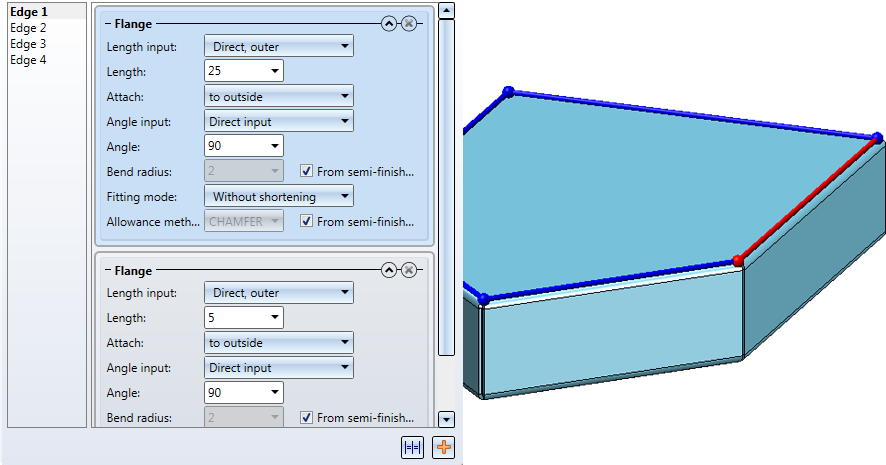
The user guidance texts of the Fold flange function have been revised:
![]()
HiCAD 2016 (Version 2100.0) will be the first version that does not contain HiCAD Unfold.
![]()
For the attaching of a flange to a surface, the following 4 options are available:

Lengths and parameters are specified in the same way for all 4 variants.
You can enter a value for the desired length. If you right-click the Length input field, a context menu with further options opens. You can then, for example, choose Pick distance to take the length directly from the drawing.
There are several options to define the reference of the length with the help of a graphic.
Likewise, the bend angle can either be entered in the Angle input field or taken from the drawing by right-clicking the Angle input field and selecting Pick angle.
The Bend radius is located at the inner side of the bend zone. If you right-click the Bend radius input field you can directly pick the radius from the drawing. For semi-finished products, the bend radius will always be taken from the Catalogue Editor.
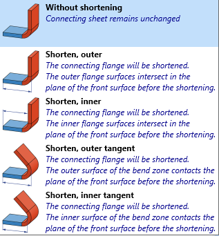
The Fitting mode refers to the processing of the connecting sheet. Here, too, the selection is facilitated by a graphical representation:
To obtain the blank (development) of the modelled Sheet Metal part, HiCAD offers you developments according to different calculation methods (allowance methods) that take the material-dependent length change of the workpiece during bending processes into account. For this, HiCAD also offers the common empirical, practice-oriented allowance methods.
The calculation methods are represented by prepared, exemplary system files. In practice, however, each user will store his own method(s) in this way. Before attaching the flange you can select the required system file.
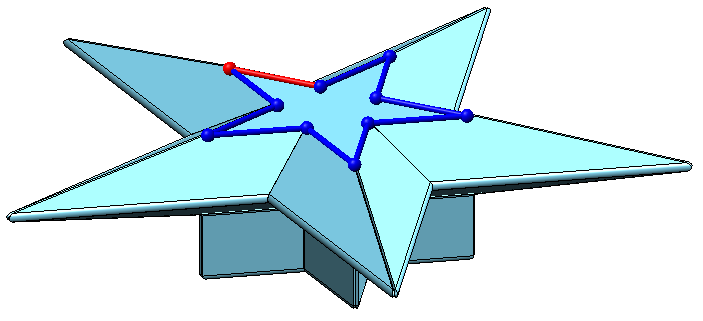
Use the Bend zone free  function to attach flanges around a surface (base sheet). The selection of the top surface determines the direction of the new flanges.
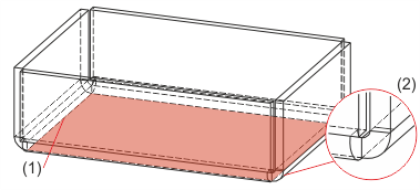
(1) Top surface
(2) Flange with free bend zone
Use the Bend zone closed  function to attach flanges with closed bend zones around a surface (base sheet). Sheets and bend zones will be lengthened up to the common intersection point of the inner edge. The selection of the top surface determines the direction of the new flanges.
Use the Drainage area  function to attach flanges with drainage area around a surface (base sheet). The selection of the top surface determines the direction of the new flanges.
(1) Top surface
(2) Flanges with drainage area
Use the Circular function to attach flanges with a circular cut-out around a surface (base sheet). The selection of the top surface determines the direction of the new flanges.
![]()
Thanks to the enhanced blank functionality you can now derive several blanks with different parameter settings from a Sheet Metal part. The parameter settings are saved in the blank. The structure of the corresponding function has changed as follows:
|
Functions |
Description |
|
|---|---|---|
|
|
Use this function to update all blanks of the active Sheet Metal part. If the blanks have different blank parameters, these will be retained, as the blank parameters are saved in the blank. |
|
|
Pull-down menu |
||
|
|
Use this function to update all blanks in the drawing, e.g. after changes to the Sheet Metal part or the parameters. If the blanks have different blank parameters, these will be retained, as the blank parameters are saved in the blank. |
|
|
|
Use this function to change the blank parameters of a selected blank. |
|
|
|
Use this function to change the blank parameters of new developments or blanks that were created with the Develop sheet function. In the dialogue window, activate the checkboxes and options for the parameters that are to be shown in the blank. |
|

|
Use this function to change the blank parameters of all developments or blanks in the drawing. In the dialogue window, activate the checkboxes and options for the parameters that are to be shown in the blank. |
|
![]()
The operation of the With sketch option in the Attach flange dialogue window has been simplified: After selecting the outer connecting edge you can only activate sketch edges, even if they are covered by a flange edge.
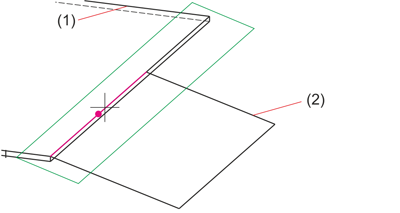
(1) Flange
(2) Sketch
![]()
The options of the Split LVD data tab have been expanded:
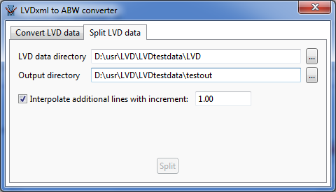
Activate the Interpolate additional lines with increment: checkbox to calculate additional intermediate values for the data in the ABW file.
Example:
The values for bend angles in the LVD data are 10°, 20°, etc.
If the increment is 2, the values for 12°,14°,16°,… will be entered into the ABW file.
![]()
The part attribute BOM-relevant can be set for all new sheets in the SYS/ABWPAR.DAT file.
# Sheets BOM-relevant (yes=1 , no=0)
1
This setting will now also be evaluated by the functions Sheet from solid and Connecting sheet functions.
![]()
Previously, only views of beams and profiles could be displayed as shortened views in workshop drawings. This is now also possible for other views, e.g. views of Sheet Metal parts etc. For this purpose, the Settings for views dialogue window (Drawing > Itemisation/Detailing > Drawing derivation - Settings for: Views) has been changed. There you can specify, beneath Shortened view, which views are to be shown as shortened views.
If you also want to display other views, e.g. views of Sheet Metal parts, as shortened views, activate the Show other views as shortened views checkbox, and enter the Minimum width of shortening area (=disappeared area) and its Distance to the relevant geometry.
If the settings for the drawing derivation are loaded from a configuration, the settings specified for the corresponding usage in the Configuration Editor at Automatic drawing derivation > Production drawing > Usage-dependent > > Fertigungszeichnung > Verwendungszweckabhängig >name > Views > Shortened view. > Ansichtsverkürzung festgelegten Einstellungen ausgewertet, with name being the name of the corresponding usage, will be used.
![]()
The three file formats 3DPDF (.pdf), Universal (*u3d) and Product Representation Compact (.prc) offer a merging of sheets during import. Select this option if you want all sub-parts of a Sheet Metal part, together with the superordinate part, to be combined into one part during export.
![]()
Related Topics
HiCAD Sheet Metal • General Notes on Sheet Metal Processing • Overview of Functions (3-D SM)
|
Version 2102 - HiCAD Sheet Metal | Date: 15/11/2016 | © Copyright 1994-2016, ISD Software und Systeme GmbH |


