
Sheet Metal > Further Tools > Mould
HiCAD Sheet Metal has a library of moulding tools which you can use to shape your Sheet Metal part. To expand the library you can use
Once you have selected the function, the Setting dialogue window appears.
The selection window with the moulding tools appears. The selection is displayed as a tree structure, as is standard in Windows.
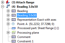
The moulding will be entered into the Feature log and can be changed with a double-click on the feature "Beading...".
You can now insert the tool individually or compile a group via the Grid menu that appears.
You can now fit the moulding a second time. Alternatively, you can use the right mouse button to activate a context menu before defining the new fitting position. The functions of this menu enable you, for example, to change the fitting direction. Use the middle mouse button to end the function.
(1) Swaging hump
(2) Centring boss
(3) Beading
(4) Extruded thread
(5) Vents
(6) Processing plane

![]()
Moulding tools are 3-D parts. In sheet development they are displayed in Hidden Line representation. To display them as 2-D symbols in sheet developments you need to create a parameterised 2-D HCM variant of the tool and enter it in the Catalogue Editor.
Proceed as follows:
The geometry must be created in such a way that the later insertion point will be located in the origin of the 2-D coordinate system.
The symbol entered in the Catalogue Editor will now be displayed in the sheet development.
 Please note:
The presetting of the line colour for the 2-D sheet development of moulding tools can be found in the ABWCOL.DAT file. After a change of the presetting, HiCAD must be restarted for the changes to take effect.
Line 31/32
# Farbe 12: Umformkanten abcform (# Colour 12: Forming edges abcform)
32511
![]()
Related Topics
|
Version 2102 - HiCAD Sheet Metal | Date: 15/11/2016 | © Copyright 1994-2016, ISD Software und Systeme GmbH |