 >.
>. Sheet Metal > Sheet development > Develop sheet
The Develop sheet pull-down menu in the Sheet development function group provides various
functions for developing (=cutting to size) a folded sheet part or any 3-D part.
The result is a 2-D development or a so-called blank. You can derive several blanks with different parameter settings from a Sheet Metal part. The parameter settings will be saved in the blank. The functions for the definition of the blank parameters can be found at Sheet Metal > Sheet development > Dev. >.
The Develop sheet function can also be accessed by right-clicking a sheet metal part and selecting the function from the context menu.
To define the representation , click the Settings icon at the top right of the screen.
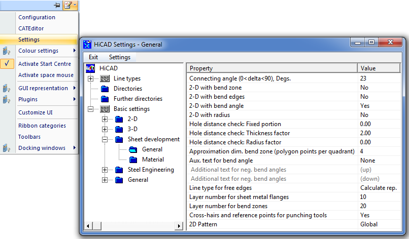
At Basic settings > Sheet Metal Development > General, you can also choose whether you want the 2-D blank to be available globally or to be only assigned to the active sheet.
 Please note:
To ensure an error-free processing, e.g. during laser cutting, the line elements must not be smaller than the laser beam. Before creating the development you can set a minimum line length. In this way it is ensured that, for example, the length of circular arcs will not fall below this minimum length during development.
You specify the minimum value in the CAM-relevant minimum length of development entry in the ABWPAR.DAT file in the HiCAD SYS sub-directory .

(1) Segment of an arc
| Functions | Description | |
|---|---|---|
|
|
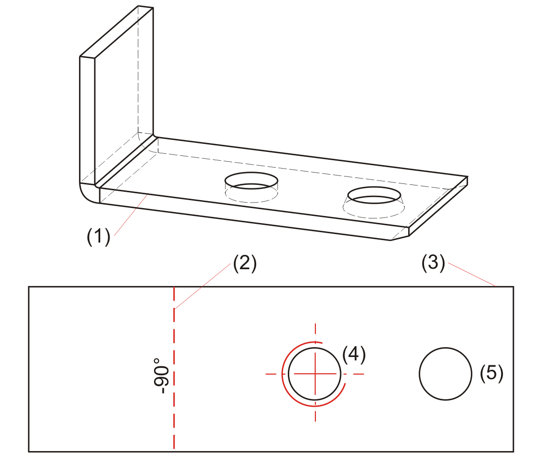
This function generates the development of a sheet part without displaying the hidden edges. Identify an edge of the basic sheet. The development then attaches to the cursor and can be freely positioned in the drawing.
(1) Base sheet If you activate the automatic sheet development (right-click) instead of selecting the base sheet when developing a sheet part, the side with the processing direction arrow will be developed. If the sheet part has nor processing direction, the coated side will be developed. |
|
| Pull-down menu Dev. |
||
|
|
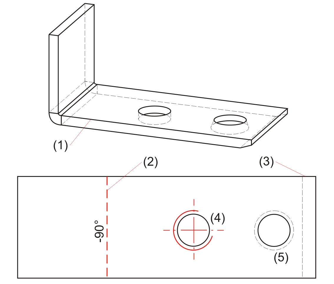
This function generates the development of a sheet part. The hidden edges are displayed dashed. Identify an edge of the basic sheet. The development then attaches to the cursor and can be freely positioned in the drawing.
(1) Base sheet If you activate the automatic sheet development (right-click) instead of selecting the base sheet when developing a sheet part, the side with the processing direction arrow will be developed. If the sheet part has nor processing direction, the coated side will be developed. |
|
|
|
You use this function to develop the lateral surface of a 3-D part, taking into account the connecting angle In other words, all surfaces that do not exceed the connecting angle are taken into account.
The sheet thickness will be queried in case of a possible length change, which makes sense for cylindrical surfaces. For all other surface types the query can be skipped with a right-click (RMB = No length change).
(1) First edge
|
|
|
|
You use this function to develop the lateral surface of a 3-D part and its sub-parts, taking into account the connecting angle. In other words, all surfaces that do not exceed the connecting angle are taken into account. The sub-part must be added to the main part below the connecting angle.
The sheet thickness will be queried in case of a possible length change, which makes sense for cylindrical surfaces. For all other surface types the query can be skipped with a right-click (RMB = No length change).
|
|
|
|
Use this function to develop the outer shell of a 3-D part (e.g. a truncated cone) analytically. You are always prompted to specify an offset (sheet thickness) for the cutting depth. For filleted surfaces, this will cause changes of the surface area of the developed object.
When developing freeform surfaces, the sheet thickness always need to be set to 0, and automatic sheet thickness detection (RMB) must not be started!
For freeform surfaces: 0.
The tear-open point determines the cutting line in the lateral surface.
|
|
|
|
Use this function to start automatic sheet thickness calculation immediately after identification of the surface of a 3-D part (solid, freeform surface). After calculation of the surface thickness, the offset will be set, without any further entries, to half of the sheet thickness, i.e. the development takes place on the neutral axis. If the sheet thickness cannot be calculated, an input window appears. For freeform surfaces you always need to set the sheet thickness to 0.
The tear-open point determines the cutting line in the lateral surface.
|
|
 Please note:
If desired, you can you can suppress the export of chamfers, countersunk holes and thread lines via corresponding settings in the the system file ABWPAR.DAT.To do this, you need to change the colour of the chamfered edges in the ABWCOL.DAT file beforehand. For the following parameter:
Farbe der gefasten Kanten in der 2D-Abwicklung (-1 = wie Umriss) [=Colour of chamfered edges in 2-D development (-1 = same as contour)]
enter, for example, a 7 for green. Then, change the following parameters in the ABWPAR.DAT file as follows:
Consider non-contour edges for DXF export (1/0)
0
Consider thread lines for DXF export (1/0)
0
After this, restart HiCAD. Chamfers and thread lines will then no longer be considered for DXF file export.
![]()
Related Topics
Function Overview • General Information on Sheet Processing • Blank Parameters
|
Version 2102 - HiCAD Sheet Metal | Date: 15/11/2016 | © Copyright 1994-2016, ISD Software und Systeme GmbH |


 Please note: