Automatically Place Parts on Guidelines
Plant Engineering > Guideline Tools > AutoPlace parts on guidelines 
This function enables you to automatically place the following part types on guidelines:
- Counter-flanges at guideline start and end points, if the guideline begins or ends with a flange and the respective flange has the same nominal diameter and pipe class assignment as the active pipeline,
- Elbows; these can only be placed on guideline corners if a corresponding record with the appropriate angle value exists in the database,
- T-pieces,
- Straight pipes,
- Knees (with selectable insertion direction),
- Reducers,
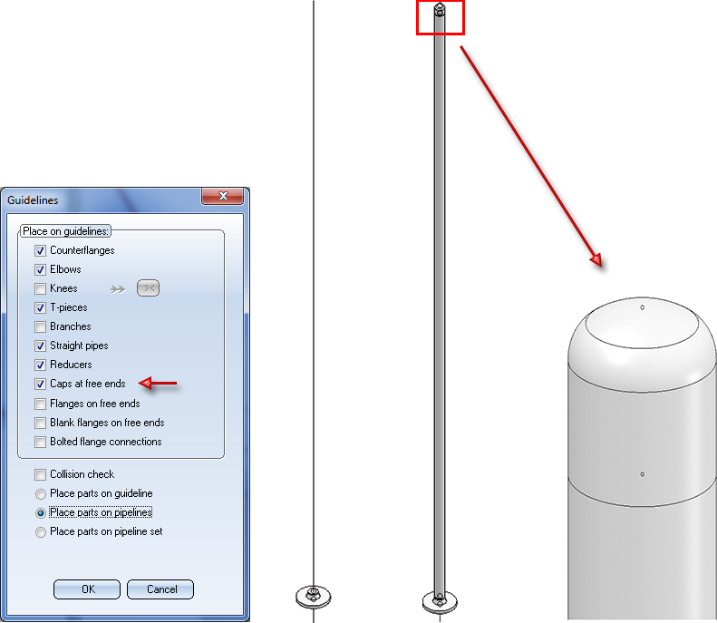
- Caps on free ends
- Flanges on free ends,
- Blank flanges on free ends,
- Bolted flange connections.
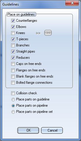
The procedure of the function depends on the parameters you specified via Settings: Place parts on guidelines. By default, the Guidelines dialogue window will be displayed. Specify, by activating the appropriate checkboxes, which parts you want to place on the guidelines.
Collision check
If you want to automatically start a collision check. after successful part insertion, activate the same-named checkbox. HiCAD will then check whether the pipeline collides with other parts in the drawing, it does not check whether the parts within the pipeline interfere with each other.
Pipeline selection
Active part
Here the pipeline to be assigned is determined via the active part. If the active part is a guideline, parts will be placed only on this guideline. Otherwise the parts will be placed on the superordinate pipeline. If the active part has no superordinate pipeline, the dialogue behaves as with the Place parts on pipeline option.
If several parts are selected, of which at least one is a sub-part of a pipeline, the options are greyed out and the elements to be assigned are determined via the multiple selection. Analogous to the selection via the active part, parts will be placed on individual guidelines. For each other selected part, parts will be placed on the respective superordinate pipeline.
Place parts on guideline
If several guidelines can be assigned to an active pipeline, and you do not want to place parts on all of them, you can select one particular guideline and place parts only on this guideline. Activate the Select guideline checkbox. After exiting the dialogue window with OK, HiCAD prompts you to identify the guideline.
Place parts on pipeline
If you want to place parts on all guidelines of a pipeline, activate this option. After exiting the dialogue window with OK, HiCAD prompts you to identify the pipeline.
Place parts on pipeline set
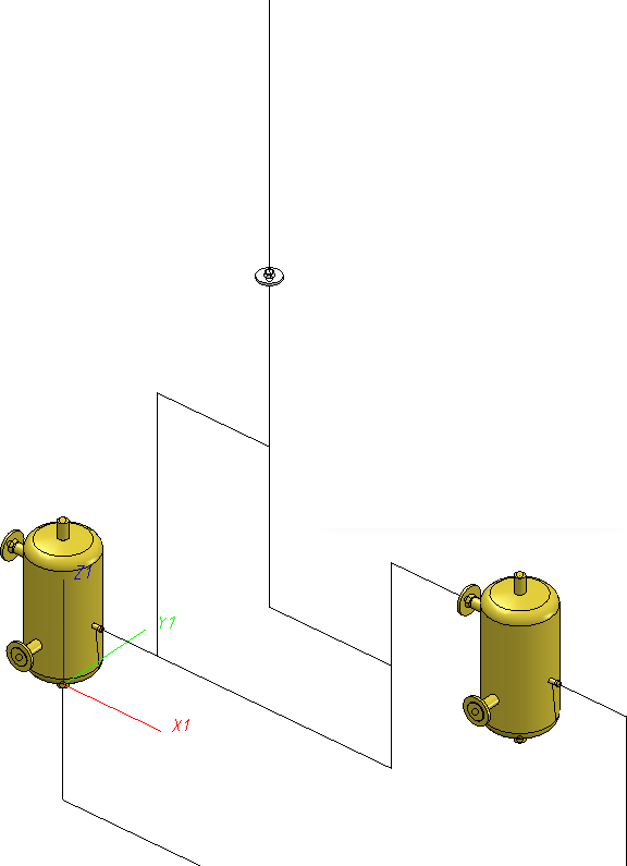
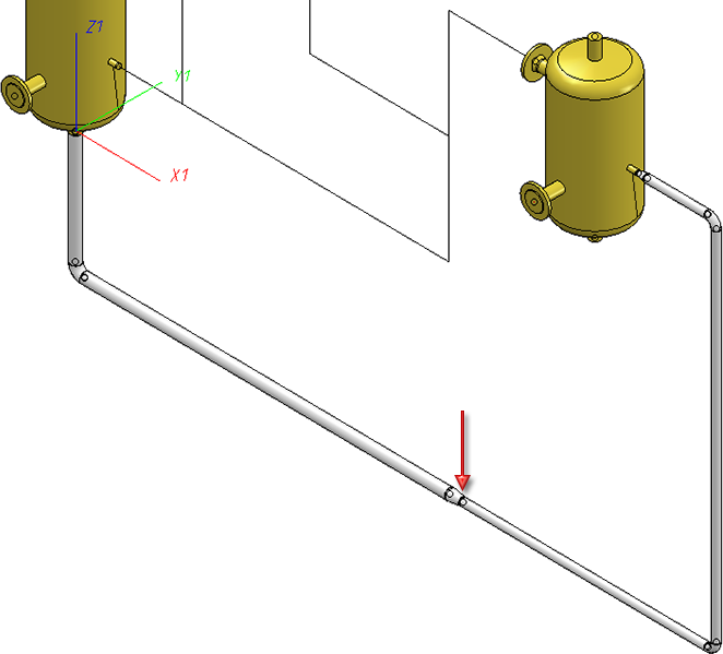
This option offers the option to interpret several connected pipelines as one pipeline set and place parts on them in one step. After existing the window with OK, HiCAD prompts you to select the pipeline set. In the image below (left), a new pipeline begins on the single flange.
If you have chosen the Place parts on pipeline set option, parts will be placed on the pipeline set in such a way, as if the pipeline set was one single pipeline.
When you exit the window with OK, HiCAD will start with the automatic placing of parts.
If a part for a particular fitting situation needs to be found during automatic placing of parts, an appropriate search window will be shown. This search window can belong to a different application, e.g. HELiOS. If such a window is shown, HiCAD will not allow any inputs, i.e. you cannot navigate in such a situation.
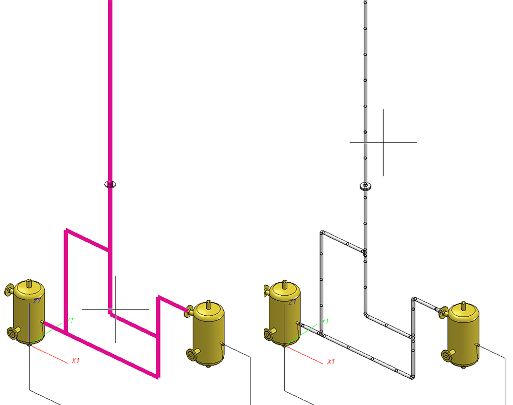
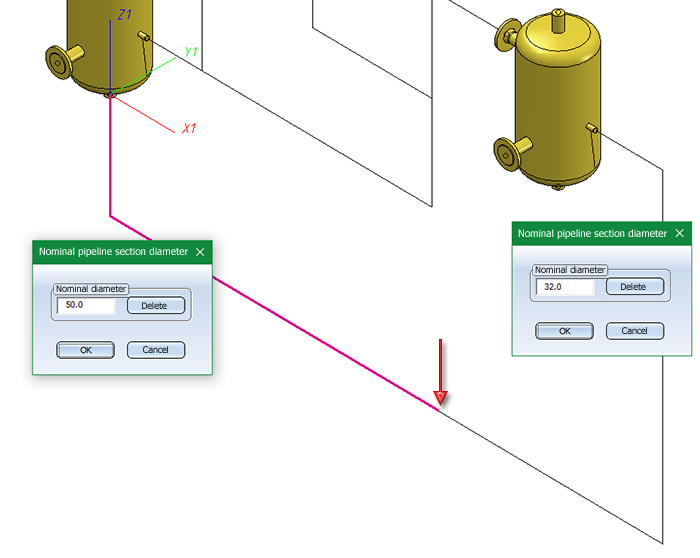
For the sake of a clearer overview, a second window with an enlarged detail view of the current fitting situation will be shown. This means that the drawing area is split into two areas during automatic part placing: On the left an overview of the complete pipeline is shown; on the right, an enlarged representation of the concrete fitting situation is shown. In both representations, an arrow pointing at the current fitting situation is displayed. The direction of the arrow corresponds to the viewing direction in the detail view.
Example:
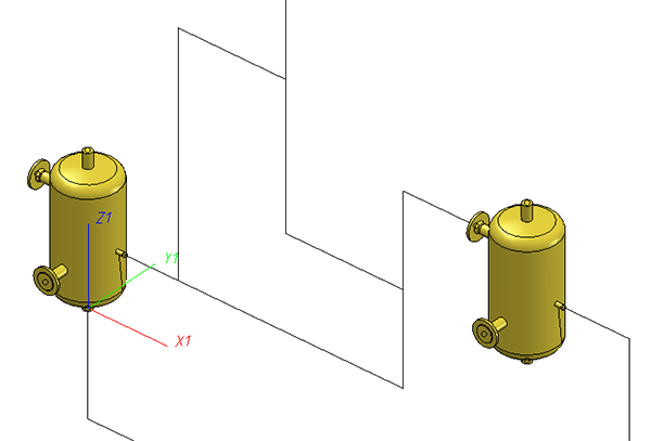
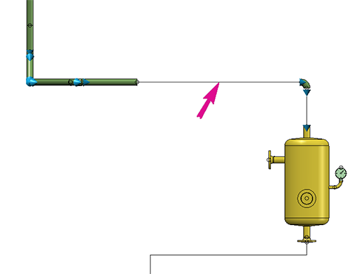
The following example shows the original drawing, where the automatic placing of parts initially sets a counterflange:
If you now start the automatic placing of parts, the following will be displayed as soon as the search window offers concrete flanges for selection:
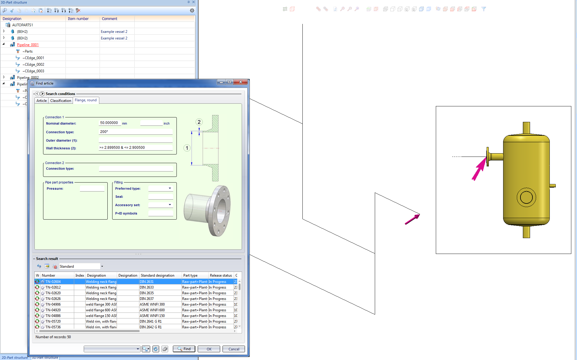
The vessel will only be displayed in the detail window, as it does not belong to the pipeline. This representation serves the purpose of a clearer overview, since vessels are normally the larger parts. In the detail view, longer parts, such as pipes and guidelines, are sometimes only implied: In the present example, a portion of the guideline is implied by means of a dashed line. This representation, too, servers the purpose of a clearer overview.
 Please note:
- If HiCAD issues an error message ("Invalid edge…" or similar), please make sure that the pipeline associated with the guideline is active. If this is not the case, please activate it. If HiCAD re-issues the message, the selected composite edge is not a guideline.
- If several guidelines can be assigned to an active pipeline, and you do not want to place parts on all of them, you can select a specific guideline and place parts only on this guideline. Proceed as follows:
- On the Plant Engineering tab, choose Settings > Settings
 > Settings: Place parts
  .
. - Activate the Always display this dialogue checkbox. If required, define further settings and exit the window with OK.
- Call the AutoPlace parts on guidelines function again. The settings window is displayed and you can proceed as described above.
- The insertion type Connect automatically applies when placing straight pipes onto guidelines, filling the gaps between already inserted parts.
- If a composite edge includes a succession of edges containing one or several circular arcs, but no corners, a bent pipe will be placed onto this composite edge.
- When placing parts on pipelines with the AutoPlace parts on guidelines function, you have the option to automatically consider weld gaps. These will be visible as gaps between the parts in the layout plan. On the Weld gap tab of the Plant Engineering Settings dialogue window you can choose whether or not to consider weld gaps, and select the procedure for weld gap width calculation.
- We also recommend reading the information given in the chapter Automatic Adjustment of Nominal Diameter Condition.
- If the Use presettings for placing of parts on branching points checkbox on the Part placing on branching points tab of the Plant Engineering Settings dialogue is active, and nominal diameters have been assigned to all guidelines, the selection of the part type, connection type (and, if required, the standard designation) for the corresponding branching point will take place automatically. lf not all nominal diameters havebeen preset yet, they will be queried.
- During part placement an arrow pointing on the currently processed edge will be displayed. The size of that arrow can be specified in the Configuration Editor at Plant Engineering > Layout plan. The value must be between 10 and 300 pixels, the default value is 80.
If you select neither elbows nor knees, but straight pipes, mitre cuts will be applied to the straight pipes, e.g. like this: 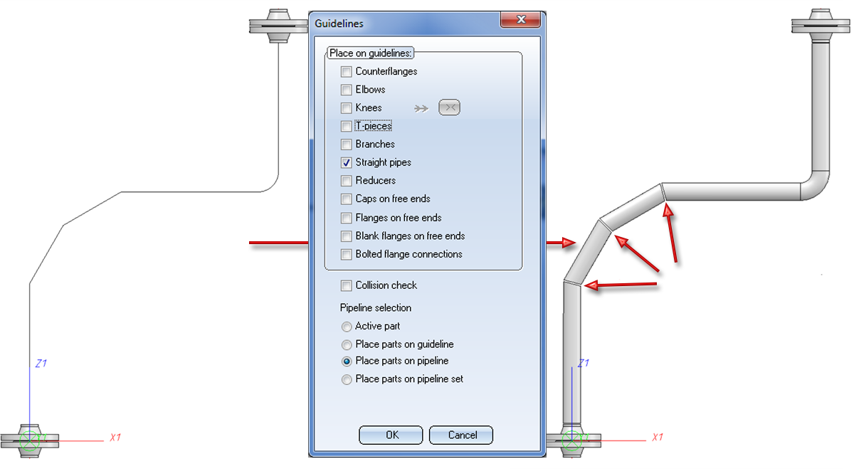

Counterflanges
When connecting flanges, the search criteria for the flange to be fitted always refer to the flange connection to which the flange is to be attached. This means that the nominal diameter assigned to the pipeline or the guideline is always ignored, i.e. even if the Ignore nominal diameter option has not been activated. If the flange connection to which the part is to be fitted belongs to a flange, the same flange is inserted as a counter-flange; this applies even if a pipe class not containing this flange has been assigned to the pipeline.
Reducers
If a nominal diameter has been assigned to the active pipeline, or if at least to the guidelines of this pipeline, HiCAD inserts an appropriate reducer in each part connection whose nominal diameter differs from the nominal diameter at its insertion position. If a pipe class has been assigned to the pipeline, this pipe class needs to contain the appropriate reducers.
Automatic placing of parts on guidelines also supports reducers on guideline transitions. The function will then place reducers in places where there is a transition between guidelines of different nominal widths.
Such a reducer is placed midway on the transition:
Caps on free ends
This option automatically places caps on vacant guideline ends (i.e. the start or end of a guideline). A guideline end is vacant if no part is located on the end point, and the end point is not located on the connection of a part that does not belong to the active pipeline.
This checkbox is activated if the Flanges on free ends is deactivated.
Flanges on free ends
Use this function to automatically place flanges on free guideline ends ("ends" meaning start points and end points of guidelines). A guideline end is "free" if no part is attached to it and if the end is not located on the connection of a part that does not belong to the active pipeline.
Blank flanges on free ends
Use this function to attach a blank flange to a flange which is located at the end of a guideline. In this case the blank flange will not be placed on a guideline. The search criteria for the blank flange to be fitted always refer to the flange connection to which the flange is to be attached. This means that the nominal diameter assigned to the pipeline or the guideline is always ignored, i.e. even if the Ignore nominal diameter option has not been activated.

Guideline Tools (PE) • Plant Engineering Functions • Part Selection - Catalogue or Database • Close Gaps