Working with Guidelines
If you want to work with guidelines, you need to make sure that the Work with guidelines checkbox in the Part insertion tab of the Plant Engineering Settings window is activated.
Additional requirements are as follows:
- At least one pipeline must exist.
- The required pipeline must be active.
- At least one guideline must exist.
- The appropriate directory must be set for the required representation.
In HiCAD, we differentiate between three different categories of parts:
- Parts valid for insertion on guidelines.
These are parts having two opposing pipe joints with connection surface vectors on the same axis. All parts that can be inserted with the functions: Branch, Three-way valve, Cap, Reducer, T-Piece, Valve, Flange and Straight pipe, are pipe parts. - Parts valid for insertion on guideline corners.
All pipe parts that can be inserted with the functions Elbows (with the exception of 180° bends), Knees and Corner valves belong to this type. - Parts only valid for insertion on start or end point of guidelines.
These parts do not fulfil the requirements listed under 1. 180° pipe bends and all parts in the Other pipe parts menu belong to this type. Before you can specify an insertion point for this type of part, HiCAD issues a message telling you not to insert this type of part on a guideline.
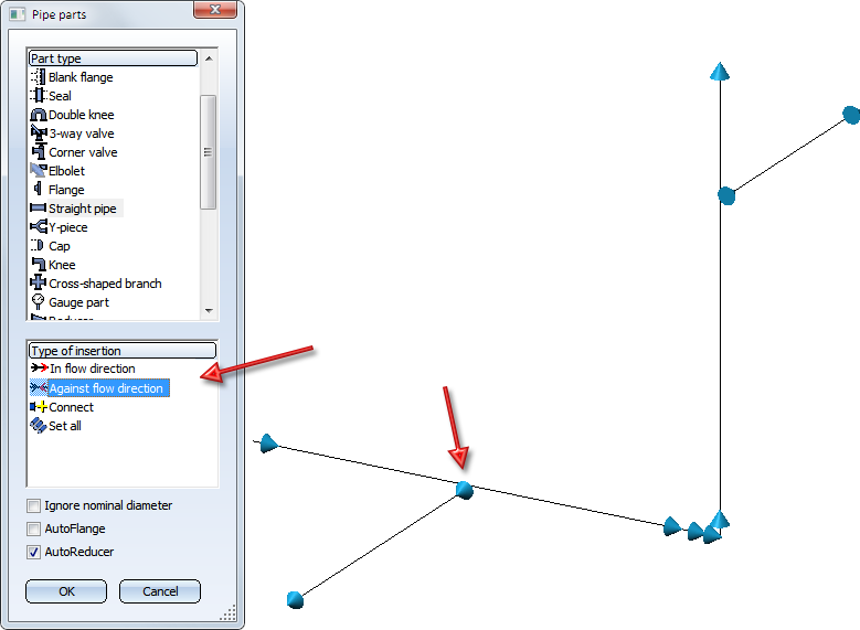
Depending on the type of part, you can select an insertion option in the lower part of the menu. After confirming your insertion option, you can change the specification by pressing the right mouse button. The following options are available for nearly all parts:
|
|
In flow direction
During part insertion in flow direction or against flow direction, appropriate flow direction arrows will be displayed:
|
|
|
Against flow direction
|
|
|
Connect
|


The selected insertion option remains valid until another part is selected. HiCAD then returns you automatically to the Part in edge direction option. Depending on the part and guideline mode selected, HiCAD offers further insertion options. In the following sections, we describe these options for individual part types.
 Please note:
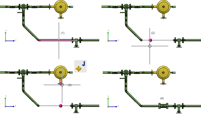
- For interactive part insertion or exchange, the cursor is used to specify the insertion position of some part categories on guidelines. In these cases, the cursor can only be moved along the guideline, whereby HiCAD displays the z-coordinate of the cursor position in the lower bar of the window (X and Y are always on 0). The z-value only accepts multiples of an automatically detected grid value based on the edge length. The exact z-value is only shown for snap functions (e.g. M). Press the left mouse button to take over the position indicated by the z-value.
- If the guideline mode is active, there is a certain priority of criteria for part search.


Pipe Parts, Components and Pipelines (PE) • Part Selection - Catalogue or Database (PE)