Settings: Part Placing on Branching Points
Plant Engineering > Settings > Plant Engineering Settings > Part placing on branching points
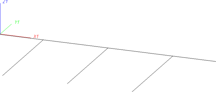
The purpose of presettings for the placing of parts on branching points becomes obvious when you take a look at the following example:
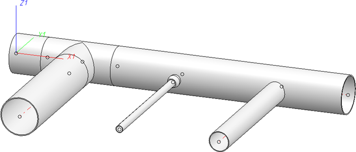
Given is a guideline for one main pipe from which several other guidelines are branching in a right angle:
On the branching points you have different options to realise the branching, e.g. by means of
- a T-piece in the main pipe,
- a part of the type "Saddle connection" attached to the main pipe, and
- a pipe directly attached to the main pipe.
Which of these possibilities can be applied depends on the nominal diameters involved. Usually, you would use the second and the third possibility, if the nominal diameter intended for the branching pipe section is significantly smaller than that of the main pipe.
An automatic placing of parts on the guidelines is only possible without any further data input, if you had previously
- assigned nominal diameters to the guidelines,
- defined for the corresponding nominal diameter mating which type of branching is to be used.
The settings on this tab have only effect on the automatic insertion of parts of the type Straight pipe.
The definition of branching points takes place on the Part placing on branching points tab of the Plant Engineering Settings dialogue.
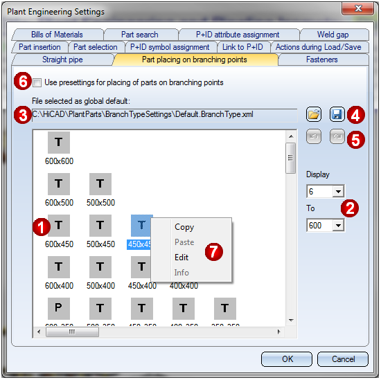
(1) Matrix window
In this area, definitions for all combinations of the predefined nominal diameters in HiCAD are symbolized (nominal diameters are in mm, and the assigned values in inches are stored in the file aninchtablew.dat in the exe\system directory of the HiCAD installation). The first number stands for the nominal diameter of the main pipe, the second number for that one of the branching (Example: 40x20). If you switch the setting in mm or inches to only in inches on the Part insertion tab, nominal diameters will always be shown in inches. A column always contains the definitions for the same main pipe nominal diameter, a row always contains the definitions for the same branching nominal diameter. As the branching nominal diameter is always smaller than or equal to than the main pipe nominal diameter, the matrix will remain empty in the right area above the diagonal.
A matrix element can also be marked with a left-click or a right-click. If you right-click, a context menu opens (7). Use the <Ctrl> and <Shift> keys to mark other elements as well. Double-clicking an element opens an editing dialogue (see (7) Edit).
The abbreviations have the following meanings:
|
T |
T-piece |
|
S |
Saddle connection |
|
P |
Straight pipe |
|
sw |
Socket-welded |
|
v |
Set standard designation |
(2) Defining the range of displayed nominal diameters
Presettings always exist for the entire, predefined range of diameters. For the sake of a clearer representation and to avoid excessive scrolling, the range can be limited to the range that is actually of interest for the user.
(3) Settings file
The definitions shown in the matrix window (1) are loaded from the displayed settings file. They represent the currently valid, global pre-settings. In other areas, the name of the selected file (without extension) will serve as the name of these special definitions. It will be saved to the Plant Engineering settings.
(4) Load settings from / save settings to file
|
|
Load settings from file Enables you to select the file the definitions in which are to be used as global presetting, or are to be modified. The file Default.BranchType.xml in the PlantParts\BranchTypeSettings directory of your HiCAD installation has been set as default by the ISD. |
|
|
Save settings to file The current state of the displayable definitions can be saved to a file. This file will then be used as the global presetting if a no different file will be loaded. |


(5) Undo / Redo
|
|
Undo Use this function to undo the changes applied in one processing step to one or several changes. |
|
|
Redo Use this function to revoke the last Undo step. |


(6) Use presettings for placing of parts on branching points
If this checkbox is active, the presettings for the placing of parts on branching points will be used. The activation refers both to the definitions in the files selected for the use of the global presettings, and to the definitions from other files that might have been assigned to pipelines.
(7) Context menu
If you right-click an element in the matrix window, a context menu with further function will be displayed. Which functions will be available depends on the status of the marked element(s) and from the actions performed before.
|
Copy |
Copies the definition of the marked element to the clipboard. |
|
Paste |
Pastes the definition that was previously copied to the clipboard to the marked element(s). |
|
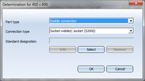
Edit |
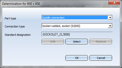
If only one element has been marked, its definition will be displayed and offered for editing.
Here you can select the desired part type and an appropriate connection type. Click Select to choose, via HELiOS part search, a part the standard designation of which is to be taken over to the definition for the marked element.
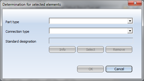
Click Info to view, via HELiOS parts search, the part(s) fulfilling the conditions given by the definitions. The option is only available if the Standard designation field has been filled in. Click Remove to remove the preset standard designation. Click OK to apply the change of the definition. Click Cancel to discard the change of the definition. If several matrix elements were marked, the dialogue will initially have no entries:
You can now enter values that will apply to all marked matrix elements after confirming with OK. |
|
Info |
Click Info to view, via HELiOS parts search, the part(s) fulfilling the conditions given by the definitions. The option is only available if the Standard designation field has been filled in. |
 Please note:
- Specifications concerning the placing of parts on branchings can be assigned to a pipeline. This takes place via the name of the file containing the definitions. The assigning can be done with the functions
- Create pipeline
 and
and - Assign pipe class and nominal diameter
 .
.
This takes place via the name of the file containing the definition. If a file has been assigned, the definitions in this file, and not those ones belonging to the file that is set as the global presetting in the Plant Engineering Settings. But the definitions in the assigned file, too, will only be used if the Use presettings for placing of parts on branching points checkbox has been activated.
The name of this assigned file will be saved, together with the other properties of the pipeline, when saving a configuration. If a pipe class has been assigned to the pipeline as well, the standard designations that may have been specified in the definitions will be ignored.
- Please also note the effects of these settings during part insertion using the functions:
- AutoPlace parts on guidelines
 ,
, - Pipe parts
 and Exchange parts
  .
.
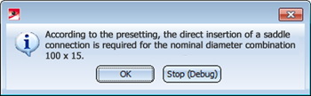
If the Use presettings for placing of parts on branching points checkbox on the Part placing on branching points tab of the Plant Engineering Settings dialogue is active, HiCAD will first ask for nominal diameters when you try to place a T-piece, a saddle connection or a straight pipe on a branching point, if these nominal diameters are not already given by the pipeline (or guideline). It will then be checked which definition applies to the current nominal diameter combination. If the part type selected for part insertion does not match the valid definition, a corresponding message will be displayed and the function will be cancelled. e.g.
- Change pipe class and/or nominal diameter of all parts

The settings on the Part placing on branching points tab will not be considered here.


Link to P+ID (PE) • Plant Engineering Settings (PE) • Pipe Parts: Flange (PE)