Motion Simulation / Physical Simulation
'Simulation' docking window
This tool enables you to simulate and animate movements of parts in an assembly. HCM constraints can also be used in the process, in order to link the movements of the parts to certain conditions. Two simulation modes are possible here:
- Motion simulation (Animation)
Enables you to assign motors to the parts to control their movements (translations or rotations). This also includes a collision check. Furthermore, you can define time intervals for the simulation. - Physical simulation
Here, too, movements are controlled by the definition of associated motors. If in this mode a moving part collides with a motionless part, the latter will also be moved as a result. Unfixed (HCM) parts will drop as a result. In this mode, the additional factor of gravity is taken into account.
 Please note that the physical simulation does not consider the moment of inertia of the parts. Therefore, acceleration processes cannot be simulated with this tool.
To define a new simulation, or edit an existing one, open the Simulation docking window: At the top right of the HiCAD screen, select  Settings > Docking windows > Simulations.
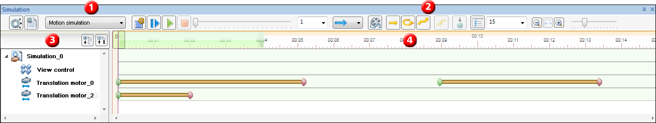
The Simulation docking window consists of four areas:
(1) Define/Edit simulations
|
|
|
|
|
|
|
|


(2) Toolbar for simulations
|
|
After defining and editing a simulation, its subsequent calculation is mandatory. Only then can the current state of the simulation be played, and saved together with the CAD drawing! |
|
|
|
|
|
|
|
|
|
|
|
|
|
|
Simple timeline Enables you to choose a particular point in time in the simulation process by moving the slider. |
|
|
Here you can specify the playing speed and the playing type (i.e. direction and repetition). |
|
|
Use this function to create a video of a calculated simulation in AVI format. |
|
Motors and Gravity |
|
|
|
A translation motor moves a part with a defined speed in a specified direction. |
|
|
A rotation motor rotates a part with a defined speed about a specified axis. |
|
|
A polyline motor moves a part with a defined speed along a defined polyline. |

|
The conveyor moves all parts of an assembly in a defined direction, along a defined surface, and with a specified speed. The movement continues until the parts lose contact with the defined surface. This surface must belong to the active simulation assembly. Conveyors are only considered for physical simulations. The conveyor function is, for example, useful for the simulation of assembly lines or sorting processes. |
|
|
This function enables you to specify the direction and the value (acceleration) of the gravity. These settings have effect on the physical simulation only. |
|
|
Settings Specifies the number of frames per second. For motion simulations you can additionally define the behaviour in case of collisions. If the Cancel calculation in case of collision checkbox has been activated, HiCAD will cancel the simulation as soon as two parts collide. In this case a dialogue will be displayed and the affected parts will be highlighted. If this option has not been activated, collisions will not be considered during the simulation. |
|
|
Maximum simulation time Here you can specify the maximum simulation time. Please note that the value must be greater than 0 and greater than the maximum of all existing switches in the timeline. |
|
|
Scaling of the timeline Use the |


 and
and  icons to shorten or lengthen the timeline bar, which can also be done dynamically by means of the slider. Clicking the
  icon displays the entire period of simulation.
(3) Simulation tree
On the left hand side of the docking window you can find the simulation tree. Here, all defined motors of the selected simulation will be listed. Newly created motors will obtain automatically assigned names (Translation motor_0, Rotation motor_1, …).
Use the  and
and  icons to expand and collapse the tree structures of simulations. The symbols in the tree structure have the following meaning:
|
|
Simulation |
|
|
|
|
View control active |
|
View control inactive |
|
|
Sequence of views active |
|
Sequence of views inactive |
|
|
Translation motor active |
|
Translation motor inactive |
|
|
Rotation motor active |
|
Rotation motor inactive |
|
|
Polyline motor active |
|
Polyline motor inactive |
|
|
Information on motor incomplete |
|
|


Right-click the name of the simulation if you want to Rename the simulation. Right -click the name of a motor to open a context menu with editing functions for motors or conveyors.
(4) Timeline
The timeline shows you the periods during which motors and sequences of views are working. These periods are defined via switches. For motors, green switches mark the start of a time period, red switches mark the end of a time period.
Newly created motors initially have always an ON switch at time "0", but no OFF switch. The time period of each motor ends at maximum simulation time. This time period must be longer than the sum of all switches.
 Please note:
- You can also enter formulae in the value input fields of the simulation dialogue. However, variables are not allowed.
- If there are missing or incorrect data when you try to close the window with OK, this will be indicated at the bottom of the window by a
 symbol. The field causing the error will be indicated by a
  symbol. If you move the cursor over the symbol, further information will be displayed.
 -
If a simulation has already been defined in the current drawing, the last edited simulation will be opened automatically.
- After playing a simulation you may need to end the simulation explicitly by clicking
 before you can select another function.

