Define / Edit Motors
You can specify the behaviour of parts during a simulation, i.e. the way how they are moved, by means of Motors.

Define motors
|
|
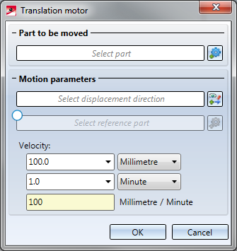
Translation motor A translation motor moves a part with a defined speed (Velocity) in a specified direction. If you enter a negative speed, the part will be moved in the opposite direction.
The translation motor will then be displayed in the simulation tree. Its name will be Translation motor_n, with n being a consecutive number automatically assigned by HiCAD. |
||||||
|
|
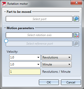
Rotation motor A rotation motor rotates a part with a defined speed (Velocity) about a specified axis. Entering a negative speed reverses the direction of the rotation.
The procedure for the definition of the rotation motor is largely identical to that for the definition of the translation motor. Instead of the direction of the movement, the rotation axis is defined here - either by identifying one edge or by specifying two points. The rotation axis will be indicated by a rotation arrow. The speed (velocity) will be determined by the number of revolutions per unit of time, or by the rotation angle per unit of time. The rotation motor will then be displayed in the simulation tree. Its name will be Rotation motor_n, with n being a consecutive number automatically assigned by HiCAD. |
||||||
|
|
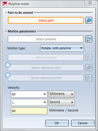
Polyline motor A polyline motor moves a part with a defined speed (Velocity) along a defined polyline. If you enter a negative speed, the part will be moved in the opposite direction. The movement types are identical to those for c-edge sweeps. The speed may also be negative.
The procedure for the definition of the polyline motor is largely identical to that for the definition of the translation motor. Instead of the direction of the movement, a polyline is identified here. In addition, you can choose a Motion type here, as you would do for the C-edge sweep function, and a reference point: Motion type:
The polyline motor will then be displayed in the simulation tree. Its name will be Polyline motor_n, with n being a consecutive number automatically assigned by HiCAD.
Reference point: Without an explicit reference point specification, polyline motors will always start at the start or end point of the polyline, and will calculate transformations in such a way as if the part to be moved was located in this position. If the part to be moved is located far away from this start point, the part will perform an unexpected movement. Similar problems occur when the part is to start right in the middle of an edge. In this situation, it is located far away from the start point and end point of the edge, thus causing unexpected movements. Such problems can be avoided by specifying a suitable reference point on the part. This reference point will be projected onto the polyline. The Polyline motor will then calculate the transformations relative to this point an the polyline, and no longer relative to the formerly chosen start point. The polyline motor will then be shown in the simulation tree. Its name will be Polyline motor_n, with n being a consecutive number that is automatically assigned by HiCAD. Click here to view an example of a polyline motor with reference point. |

 symbol and identify the desired part in the ICN or in the drawing. The part will be highlighted in red.
  icon and define the direction by identifying one edge or by specifying two points. The selected direction will be indicated by a vector symbol.
  checkbox first. Then, click the
  symbol and identify the reference part in the drawing or in the ICN. The reference part should also be a driven part, i.e. a part for which a motor has been defined.

 Please note:
- A part can be used simultaneously in different motors.
- Simulations can be played forwards and backwards. The playing type will however not be considered for the calculation of the simulation. This problem can be solved by adding another motor with almost the same data, but working in the opposite direction. The time interval of this motor must follow the time interval of the first motor. For the videos the details of the forward and backward simulations can be specified in the Create video dialogue window.
- The Polyline motor option is not available in the Physical simulation mode.
- Motors can also be defined while defined while the parts are in motion. To ensure that the new motors will actually be considered in the simulation, it must be recalculated.
Edit motors
To edit the parameters of a motor, double-click the name of the motor in the simulation tree. A dialogue window will be displayed. In your drawing, the part and (depending on the motor type) the direction of movement, the rotation axis (or the polyline, respectively), will be highlighted.
Change the settings as desired and close the dialogue window with OK.
After this, recalculate the simulation!
Right-clicking the name of a motor in the simulation tree opens a context menu containing further editing functions for the motor:
A deactivated motor will not be considered for the calculation of the simulation. A deleted motor can be restored via UNDO.
Whether a motor is active or inactive is indicated can be seen by a corresponding symbol in the simulation tree. The symbols in the tree structure have the following meaning:
|
|
Translation motor active |
|
Translation motor inactive |
|
|
Rotation motor active |
|
Rotation motor inactive |
|
|
Polyline motor active |
|
Polyline motor inactive |
|
|
Information on motor incomplete |
|
|


Please note:
The length of a time interval can be taken over as a time value for the speed (velocity) of a motor. Right-click on the timeline and select Apply time. The dialogue window for the motor will then be displayed, and the changed value will be highlighted in red.

The 'Simulation' Docking Window (3-D) • Simulation: Examples (3-D)