 /
/ 
Project: HiCAD Parametrics
3-D Standard > HCM > Toggle visibility of degrees of freedom /
The Toggle visibility of degrees of freedom function activates or deactivates the display of the degrees of freedom of a HCM system in your drawing.
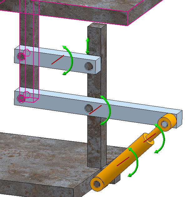
Arrows at the parts show you which transformations are still allowed in the HCM model.
These will only shown for direct sub-parts of the active assembly, and only if a HCM system exists (i.e. if at least one positional or dimensional constraint has been assigned). If the assembly contains further assemblies, these will be treated as one part. The arrows of this assemblies will then be shown in the centroid of a bounding box.
Furthermore, the degrees of freedom of a part will be shown when you click on the Sort by geometries button in the HCM tab and then select a part in the list. If the visibility of the degrees of freedom has been activated at this point, the degrees of freedom belonging to this part will be highlighted in the graphic.
Degrees of freedom will only be shown on parts which are displayed big enough on the screen. If you downsize it too much with the Zoom function, the arrows will no longer be visible. Also, arrows will only be shown if a part actually has any degrees of freedom left. If a part is fully defined, no arrows are shown.
The arrows in the centre indicate along which axes the part can be moved. As soon as a free moving is no longer possible, because this is prevented by certain constraints, the arrows will also show the direction of the movements that are still possible.
The arrows on the outside indicate about which axes the part can be rotated. The arrows indicate only the direction of the axis; their position with regard to the part is determined by the body centroid of the part., and not by the position of the rotation axis.
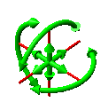
The symbol above indicates that the corresponding part can still be rotated freely, but can only be moved along the two displayed axes.
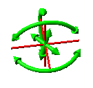
Here, a rotation is only possible about one axis. The part can still be moved along two axes.

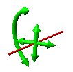
Here, a movement is only possible along one axis. No rotations are possible any more.
![]() Please note:
Please note:
The orientation of the axes only represents a "snapshot" of the situation at exactly the current position of a part. For instance, if the position is determined by a distance constraint with regard to the origin, the part can be moved along a circular path around the origin; however, the move options will still be indicated by two straight arrows.


|
© Copyright 1994-2019, ISD Software und Systeme GmbH |