Project: HiCAD Parametrics
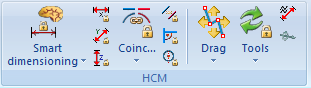
In the HCM function group of the Sketch Ribbon tab you find the functions  Coincidence,
  Parallel,
  Perpendicular and
  Fix/unfix geometry.
Clicking  below the Coincidence icon opens a pull-down menu with further Positional constraints functions.
These functions enable you to assign positional constraints, such as parallelism, coincidences, symmetry, tangency or concentricity, to graphical elements.
| Function | Description | |
|---|---|---|
|
|
Fix/Unfix geometry |
Fixing individual elements constitutes a very special constraint. If an element is fixed, it will not be moved during any required transformations. Edges, circles/circular arcs and all points found using point option I can be fixed. Identify the element or the point. If you have identified an already fixed element, the fix is removed. |
|
|
Coincidence |
You use this function to define coincidences of composite edge elements. You can do this between two points, two edges, point on edge and point on circle. This either merges elements together or ensures that a point can only move gradually on another element. Identify the two elements/points. Also bear "unboundedness" in mind here, i.e. a coincidence between a point and a line does not necessarily mean that the point lies on the line between the two bounding points, but only that it lies on the straight line through these two points. |
|
|
Parallel |
This function enables you to align two edges or a surface and an edge in parallel. Identify the two elements. The second element is aligned in parallel to the first element and the composite edge model adjusted accordingly. |
|
|
Perpendicular |
By specifying a perpendicular constraint, you ensure that lines and planes are positioned perpendicular to one another. The straight line of the first identification then stands perpendicular to the second identification. |
|
|
Align to CS axis |
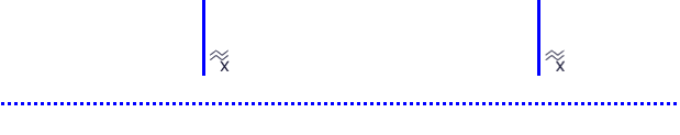
If you apply this positional constraint to a straight line of a sketch, HiCAD determines to which CS-axis the straight line has the smallest angle. A Parallel constraint will then be applied to this axis. For planar sketches you can also apply this constraints to 2 points. In this case the angle between a virtual straight line running through these 2 points and the CS axes will be considered. An Equal distance constraint with regard to this CS axis will then be applied for the 2 points.
Original situation: The dotted line represents the X-axis
After applying the Align to CS axis function to the 2 end points of the straight line |
|
|
Tangential |
A tangential constraint enables you to achieve tangential transitions between a line and a circle/circular arc, a line and a cylinder, a line and a sphere or a circle and a surface. Also bear chirality in mind with tangential constraints. |
|
|
Concentricity |
You can assign this constraint between a circle/circular arc and a point, a circle/circular arc and a line, two circles/circular arcs, a circle and a cylinder, a circle and a sphere. |
|
|
Mid-point |
This function enables you to fix a point on the perpendicular of a centre line between 2 geometry elements of a sketch. Step 1: Identify the 2 geometry elements that you want to be the reference points. Step 2: Specify the mid-point to be fixed. |
|
|
Symmetrical |
You use this function to assign a symmetry constraint between two lines, two circles/circular arcs, two points. To do this, first define a symmetry plane and then specify two reference geometries in each case. |
|
|
Equal distance |
This function enables you to assign the same distance as between two other elements to two geometry elements of a sketch. Identify 2 geometry elements. Between these 2 elements the equal distance as the one between the other element pairs of this constraint will be preserved. Please note that there is no dedicated reference distance here, i.e. the distance between all element pairs can indeed change. The constraint just ensures that it remains equal everywhere. If you specify a dedicated reference distance and want to preserve it, you need to fix the distance of an element pair by means of a different constraint, e.g. a dimensional constraint or the Fix function. Press the middle mouse button to end the function. |
|
|
Equal radius |
Use this function to assign the same radius to two circles and or circular arcs of a sketch. Identify the circles or circular arcs to which you wish to apply these positional constraints. |
|
|
The effect of this positional constraint is that two angles will always have the same value. Identify two angles, either by selecting an arc or by selecting two straight lines. |
|
|
|
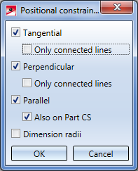
Use this function to automatically assign positional constraints between suitable elements in a sketch. After calling the function you can specify which positional constrains are to be searched, and whether they should only be applied between connected lines, or also to elements that are independent from each other.
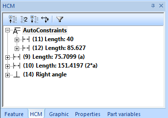
The Also on Part CS option option refers to line elements running parallel to an axis (or, in 3-D sketches, also parallel to a plane) of the Part CS. If this option is active, Parallel constraints with regard to this axis or plane will be set. If you deactivate this option, Parallel constraints will only be assigned between parallel line elements. Constraints created with this function can be found beneath a separate item called AutoConstraints. If desired, you can move these constraints out of this item via Drag & Drop , or choose the context menu function Remove from AutoConstraints to move the constraint out of the AutoConstraints item and list it among the "normal" constraints instead.
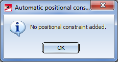
If no positional constraints have been created, the following message will be displayed:
|
|
The Others menu item you will find an additional menu with Spline property functions.
Positional constraints containing a reference to an axis or plane of the coordinate system will be given particular attention: For instance, a parallelism constraint referring to the X-axis of the Sketch CS will not just be listed as Parallel in the ICN, but as Parallel to X.
Positional constraints are represented by means of the following symbols in the drawing:
|
|
Tangential |
|
Coincident |
|
|
Perpendicular |
|
Parallel |
|
|
Concentric |
|
Mid-point |
|
|
Symmetric |
|
Equal distance |
|
|
Equal angle |
For constraints that can also contain references to coordinate system axes or planes, variants of the respective symbols are provided, showing you to which axis or plane the constraint refers. These variants are shown in the table above.
In the Configuration Editor at System settings > Annotations > HCM_Symbol you can influence the display of these symbols: Besides symbol and background colours you can also specify the size of the symbols here.
![]() Please note:
Please note:
When you call one of the functions for assigning of positional constraints, the coordinate system for 3-D sketches will be activated automatically if the respective function works with this coordinate system. When you end the function, HiCAD will switch back to the previous coordinate system.


3-D Composite Edge Constraint Manager
|
© Copyright 1994-2019, ISD Software und Systeme GmbH |