Sheet Metal - What's New?

Service Pack 2 2024 (V 2902)
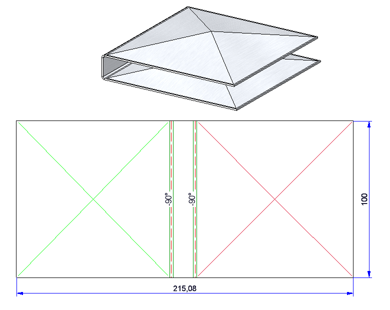
Cross-breaks in developments
In sheet developments, cross-break edges previously used the same setting as forming edges.
As of HiCAD SP2, you can set the line colour, line type and layer in the Extended settings  on the Edges and lines tab for
-
Cross-breaks with positive bend angle and
-
Cross-breaks with negative bend angle.
Manual changes to developments
Previously, automatically generated dimensions and annotations of a development that were changed manually were reset with the Update development  function. As of HiCAD SP2, all changes to the position and the properties (e.g. bracketing of the dimension figure) will beretained after synchronisation. This change affects all texts generated by the Develop sheet
  function via the options Dimensioning and Annotation > Bend line texts.
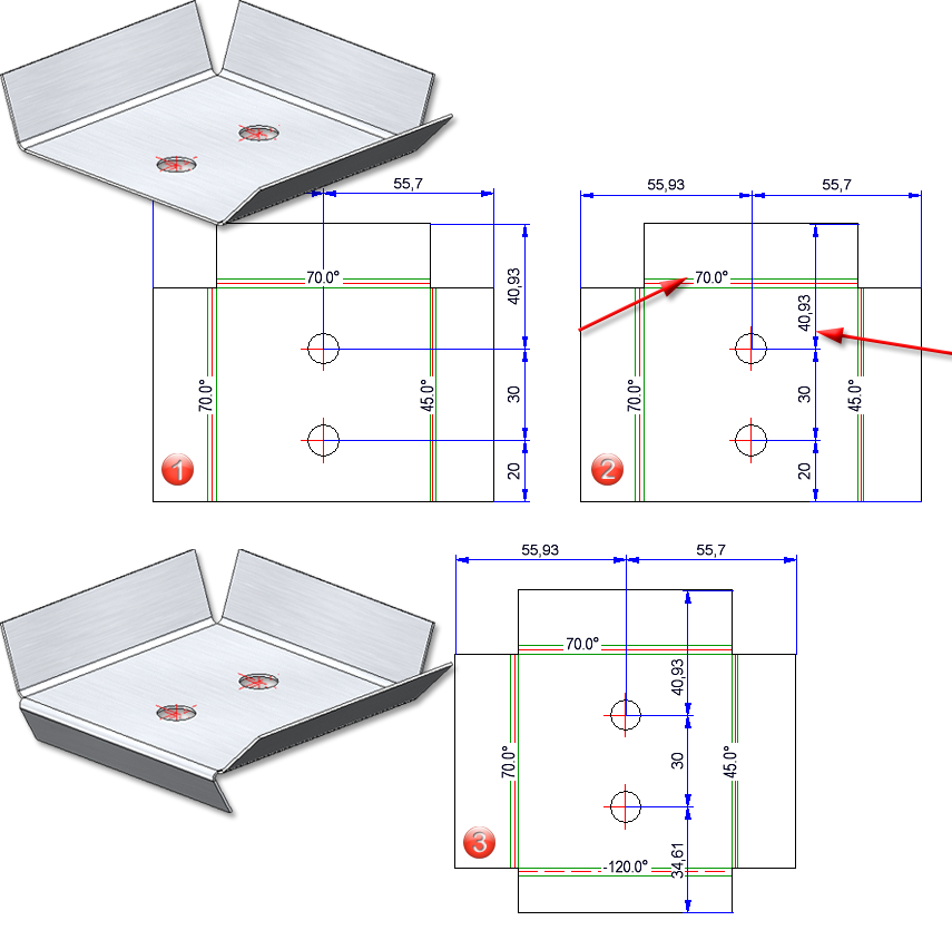
(1) Dimensions and annotation of the bend lines are generated automatically,
(2) Chain dimension and bend angle are moved manually,
(3) After processing the sheet and updating the development, the changes are retained.
Semi-finished product parameters
If you deactivated the semi-finished product in the sheet metal creation feature before HiCAD SP2, an error message was displayed for the parameters (bend radius) that were loaded from the semi-finished product. As of HiCAD SP2, the parameters are also deactivated if the semi-finished product is set to No. This behaviour affects the following functions::

(1) Deactivating the semi-finished product before HiCAD SP2, (2) Deactivating the semi-finished product with HiCAD SP2
Avoid double dimensions
If you activate Outer contour, the complete contour is dimensioned. If the measurement for the Outer contour matches the measurement for the Dimension during development, only the measurement for the Dimension will now be displayed.
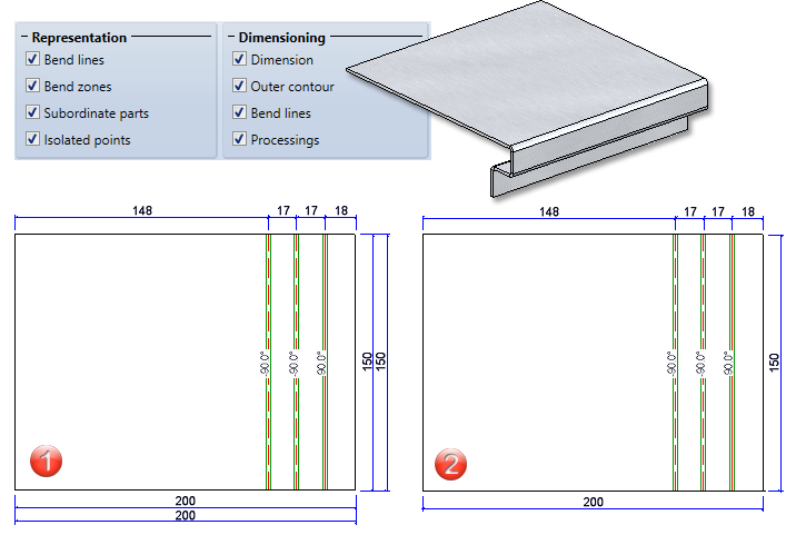
(1) Evaluation of the dimension and outer contour parameters before SP2, (2) Evaluation from SP2 onwards
Deleting flanges and bend zones
Flanges and bend zones cannot be deleted from sheet metal parts with a feature log. After activating the flange or bend zone, the entire sheet metal part is deleted. From HiCAD SP2 without confirmation prompt. Deleting flanges and bend zones is only possible in the feature log.
Free milling for sheet developments
The HiCAD API now supports the processing of sheet developments with the Free milling  function. For this purpose, there is the class
-
ISD.CAD.SheetMetal.FreeMilling
Service Pack 1 2024 (V 2901)
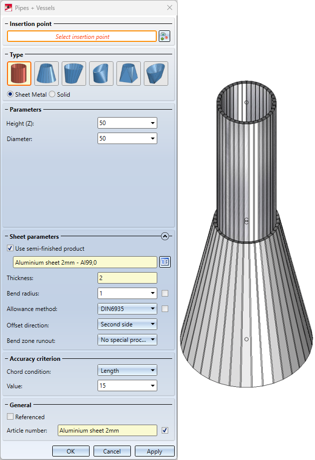
Revised Pipes + Vessels function
The Pipes + Vessels  function has been revised and made more user-friendly. As a result, you can now create parts as hollow and solid bodies in different variants and insert them as main or sub-parts.
There are six different types to choose from. You then decide whether the part should be created as a Sheet Metal part or as a Solid. The Parameters can be used to customize the parts as required.
The Sheet parameters are only active if you have selected Sheet Metal in the dialogue. You can either select a material and a thickness from the catalogue, or you can determine the Thickness in the input field without selecting a material. You also have the option of selecting a Bend radius and one of ten different Allowance methods. The Offset direction defines the direction in which the sheet is to be created. In the Bend zone runout field, you can choose from three options for how the bend zones on the edges should look. Under Accuracy criterion, you can define the Chord condition via the Angle, the Distance or the Length. You also need to enter a value that determines the accuracy of the part.
Finally, you can save the part Referenced as usual and assign an Article number. If you have selected a semi-finished product, an article number will be suggested.
Length change by selecting front edge
By default, as of HiCAD 2024 SP1, the Front edge is requested for identification in the functions for length changes of sheets. This affects the functions:
 ,
,  ,
, 
If the selection of the front edge is not suitable for the desired purpose, you can switch to the longitudinal edge with the right mouse button. In the Configuration Editor, go to Sheet Metal > Default setting and use the parameter Start mode when identifying front surfaces to change the ISD default setting from Front edge to Longitudinal edge.
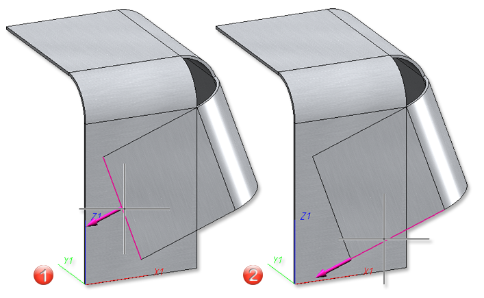
(1) Front edge, (2) Longitudinal edge
Clean up intersection
By adding the Bore out inner corners checkbox to the Clean up intersection  function, concave corners that may occur during the clean-up can be eliminated.
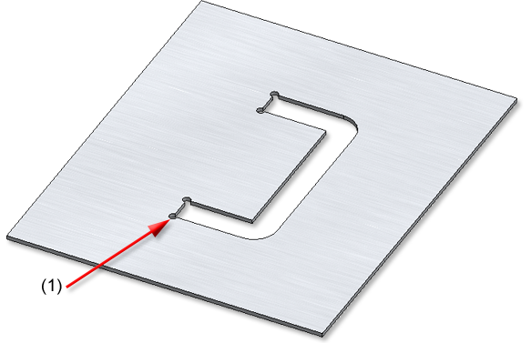
(1) The diameter of the bore can be freely selected.
Major Release 2024 (V 2900)
Feature for Sheet Metal part creation
In the function dialogues of the sheet creation, the checkbox Feature is no longer available from HiCAD 2024. This means that a corresponding feature is now always created when sheets are created.
This affects the following functions in Sheet Metal:
Sheet Metal > New > Create base sheet 
Sheet Metal > New > New sheet from sketch 
Sheet Metal > New > New sheet from 2-D development 
Sheet Metal > New > New sheet along sketch 
Sheet Metal > New > Create connecting sheet 
Sheet Metal > New > New sheet from solid 
Sheet Metal > New > New sheet from surface 
Free milling
With the new Free milling function, you can provide the edges of composite panels with a milling tool path. The tool path is defined by a sketch and the milling tool is loaded from the catalogue.
After selecting the function, first identify the sheet metal part. For the sketch, you can either select an existing sketch  and process it
  if necessary or draw a new sketch
  in the plane.
You determine the shape of the tool path by selecting the tool in the catalogue Factory Standards > Composite panels, groove form > Standard groove forms.
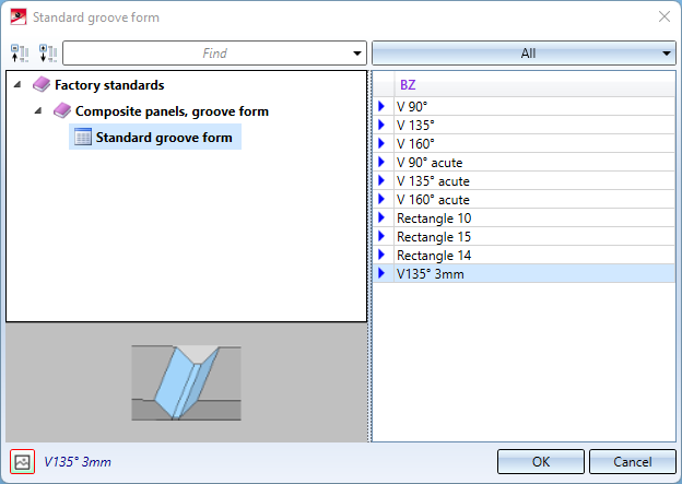
Tools for the tool path
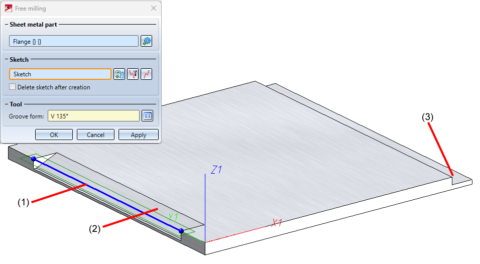
(1) Sketch, (2) Groove form: V 135°, (3) Groove form: Rectangle15
Sheet development
Exclude annotations in sheet developments
For bend line texts in sheet developments, you now have the choice of whether the text background should be left out. For this purpose, there is now the option Exclude background in the Annotation Editor.
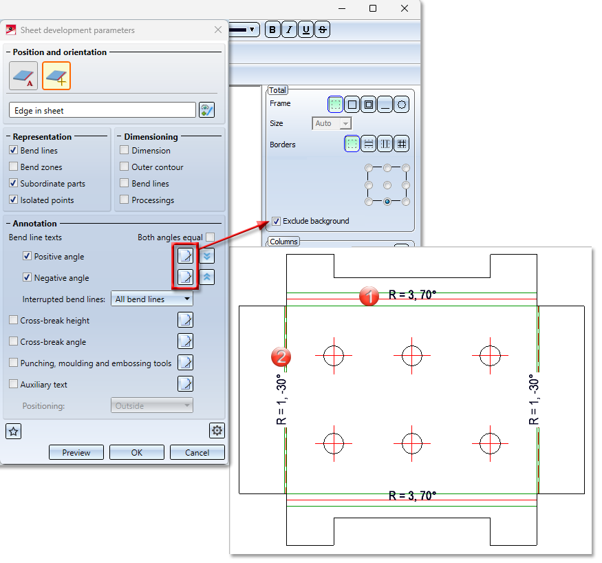
(1) Positive angle without background exclusion, (2) Negative angle with background exclusion
Display of the catalogue symbols
The development of a sheet is always a 3-D part. To exclude catalogue symbols (bore patterns, moulding tools and punching tools) from the 3-D display and to display them as symbols, activate the respective checkbox  for the sheet development in the Extended settings > Tab: Extended setting.
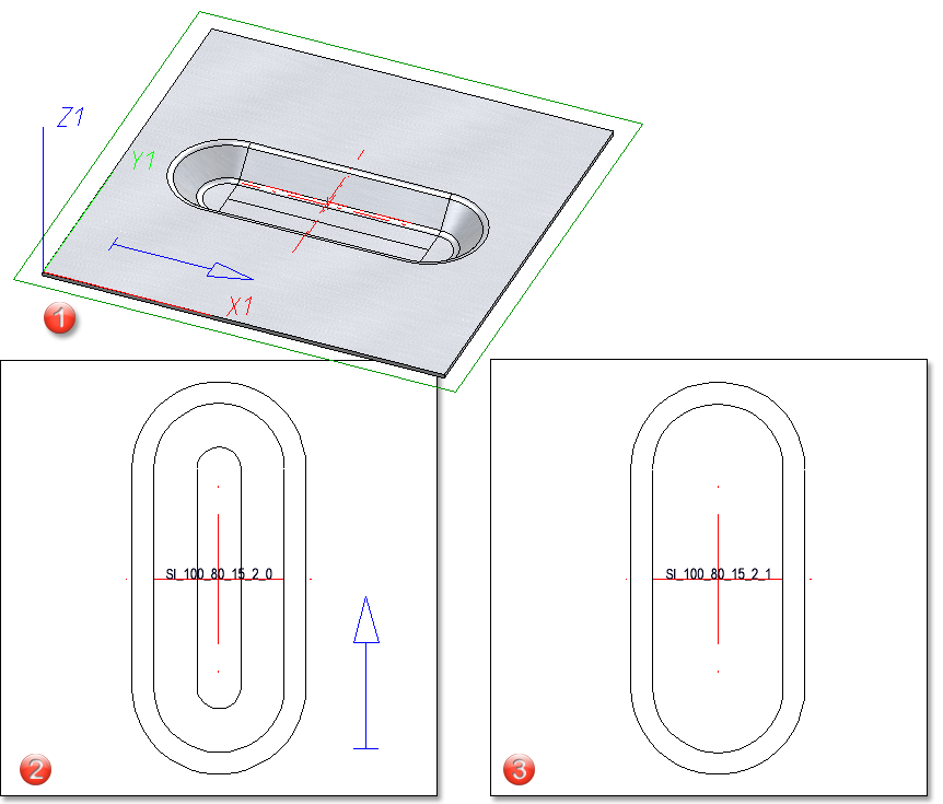
The parameters (line colour, line type, ...) of the catalogue symbols are taken from the Edges and lines tab by default. To keep the parameters from the catalogue you can now activate the new option Keep line properties for catalogue symbols.
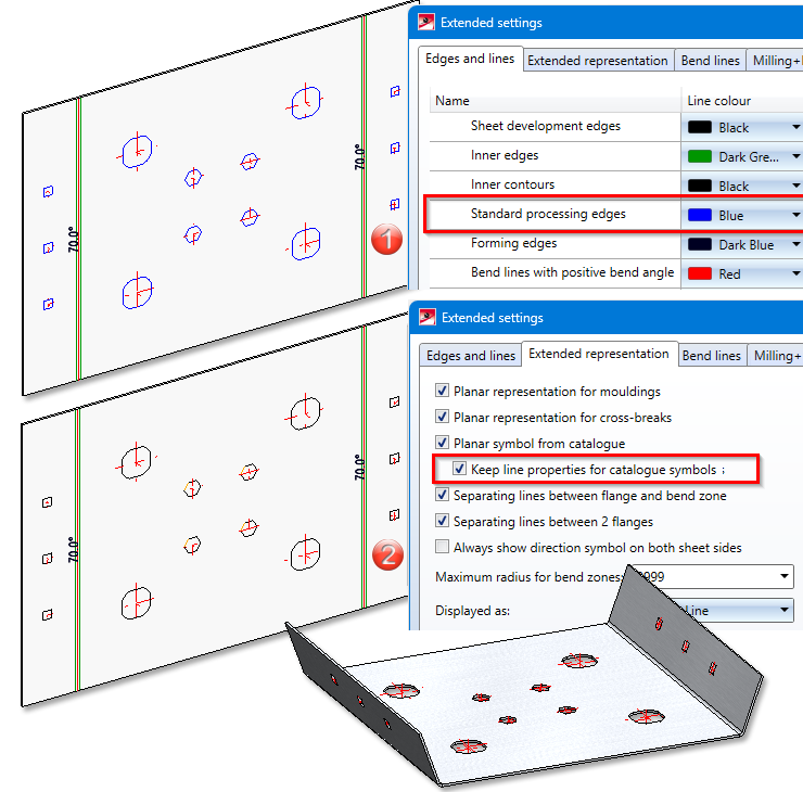
(1) Parameters of the standard processing edges changed in the Extended settings of the development.
(2) Line properties taken from the catalogue.
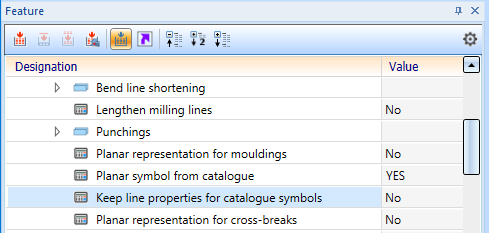
You can also change the display of the catalogue symbols in the feature.
Tool numbers in sheet metal processing
In sheet metal processing, there are machines that use different tools for processing the front and back of sheets, e.g. punch-laser combination machines. Until now you could only load different representations from the catalogue columns TOPSYMBOL and BOTTOMSYMBOL for processing the front and back side in the sheet metal development. Now it is also possible to read out different tool numbers (WZNR and WZNR_BOTTOM) from the catalogue. The catalogues for moulding, embossing and punching tools have been extended by the column WZNR_BOTTOM. If the column WZNR_BOTTOM is empty, WZNR is used instead.

(1) Table in the catalogue with WZNR and TOPSYMBOL for the front side of the development
(2) (2) WZNR_BOTTOM and BOTTOMSYMBOL for the rear side of the development
(1) Sheet with beading
(2) Development of the front side with plane representation of the moulding tool (TOPSYMBOL) and tool number (WZNR)
(3) Development of the back side with plane representation of the moulding tool (BOTTOMSYMBOL) and tool number (WZNR_BOTTOM)
Mitre with neighbouring sheets
With the Corner/Mitre function you can now add a milling edge in the Mitre, with neighbours  mode. To do this, you must activate the Sheet edge as milling edge
 ![]() option in the dialogue.
option in the dialogue.
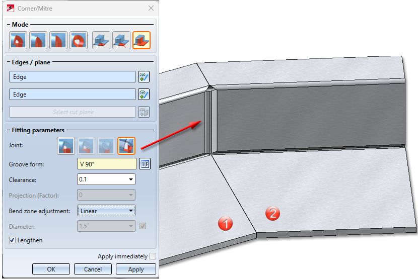
(1) First sheet, (2) Second sheet connected with milling edge zone
Apply length value
To change the length of various sheets by the same value, the function Change length  has been lextended. When lengthening sheets and bend zones, you can now fix the value for the Length specification options By value and Total length .
 With this switch position, the value (active option By value
  ) for the extension is set to 0 again after the first length change is accepted and the next edge is selected. This means that the last entry is not saved. If the Total length
  option is active, the total length is displayed here after the new selection.
 If this setting is active, the value or the total length is also available for the next edge after choosing Apply.
Extension of the coating function
HiCAD now also allows you to coat bulb plates and checker plates. You can assign different parameters (colour and description) for the front and back side.
Until now, the coating of general parts (without structure) was not displayed in section and detail views. From HiCAD 2024, the coating of general parts (without structure) is also displayed in sectional and detail views.
Settings for 2-D DXF export
The settings for exporting developments as 2-D DXF files have been revised. Important settings are now moved from the Compatibility tab to the front tabs in a user-friendly, revised version. The remaining settings are now only displayed on the Compatibility tab if they do not correspond to the default settings (values of the former acadhcad/hcadacad.dat).
The settings for DXF can be customised when exporting developments using the Edit settings function and then saved as Favourites.
Improved handling of crosshairs during bending simulations
Crosshairs in bend zones of sheets are now moved to the appropriate position during a bending simulation, provided you have activated the bend zone and not the entire sheet during the process.
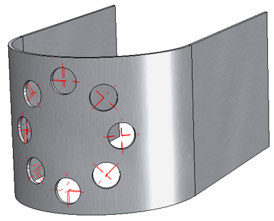
Bores forming a circular pattern in a bend zone
Transform + Clone in context menu
The context menu of flanges and bend zones has been extended by the functions for transforming and cloning parts. If the feature protocol is active, the entire Sheet Metal part is always transformed or cloned.
![]()
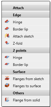
Attach flange function in context menu
In the context menu, accessible by right-clicking on a flange and then under Attach, the functions Flange from sketch and Flanges to surface can now be found:
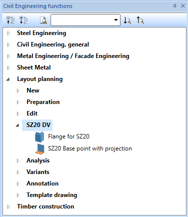
Design variant SZ-20
The Design variants
in the Civil Engineering functions docking window have been moved from Sheet Metal to Layout planning.
User-defined Steel Engineering plates in catalogue
For steel plates you can create your own tables in the Catalogue Editor at Factory standards > User-defined semi-finished products > User-defined plates. These tables are then also offered for selection in the function Steel Engineering > Plate, new > Rectangular plate.

HiCAD Sheet Metal • General Notes on Sheet Metal Processing • Overview of Functions (3-D SM)