Sheet Metal > Further functions > Extras  > Free milling
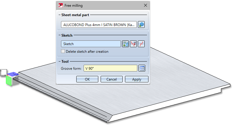
With this function you can apply a tool path to the edges of composite panels. The tool path is defined by a sketch and the milling tool is loaded from the catalogue.
-
First select the sheet metal part.
-
Then activate the sketch for the tool path.
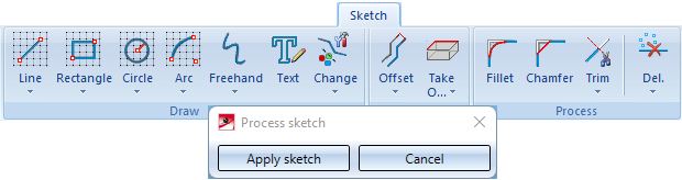
If a sketch is active in your drawing, it is automatically selected to create the milling edge. If there are several sketches, you must select the sketch. You can also call the function New sketch sketch in plane  in the dialogue and draw a new sketch with the Sketch functions. Then finish the sketching technique with Apply sketch. If you want to identify another sketch, select the
  icon in the Sketch area to identify the new sketch. To change the sketch, click the Process sketch
  icon. The menu bar with the sketch functions and the processing dialogue are displayed. Use the processing dialogue to end the sketch processing and return to the Free milling dialogue.
-
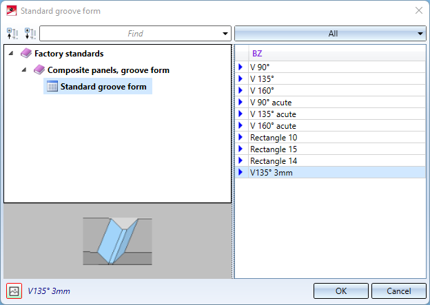
Then select the groove form.
You determine the shape of the tool path by selecting the tool in the catalogue Factory Standards > Composite panels, groove form > Standard groove forms.
Once you have entered all the necessary data, the tool path can be installed. If you select Apply or click with the middle mouse button, the tool path will be applied, but the dialogue window remains open - unlike OK. This way you can change the data and assign it to another sketch with Apply.
![]() Please note:
Please note:
Incorrect entries are indicated by this  symbol. Move the cursor over the symbol to show the error message. If the function cannot be executed with the entered data, this
  symbol appears at the OK button.
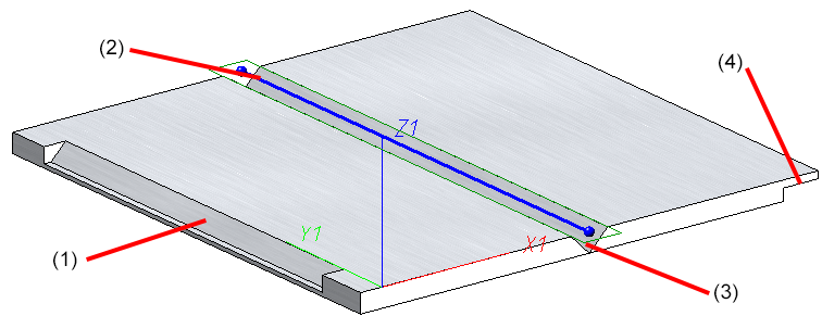
(1) Groove form V 90°, (2) Sketch , (3) Groove form V90 ° acute, Groove form Rectangle 15

