General Notes on Sheet Metal Processing
- Technology parameters
- Sheet metal main part
- Part structure
- Part attributes
- Semi-finished products
- Copy sheet
- Delete sheet
- Blank
- Part orientation
- Derived drawing
- Weld seams
- Sectional views with coating lines

Technology parameters
HiCAD Sheet Metal enables you to model different sheet parts using the technology parameters.
The technology parameters include:
- Sheet length/height
- Bend radius,
- Bend angle,
- Fitting mode or
- Clearance between added sheets.
Furthermore, you can create sheets from a 3-D body, from 2-D developments, from polylines and as an external offset of a 3-D body.
Sheet metal main part
You can only find the Sheet Main Part function in the context menu of a sheet part of the drawing. If you choose this function, the base sheet (sheet main part) becomes active, and the context menu containing the processing functions opens. The selected function is then applied to the base sheet.
Part structure
Sheet metal flanges and bend zones are created as equal sub-parts of the superordinate Sheet Metal part. The Sheet Metal parts can then be combined into assemblies or into a main assembly.
If you select a flange or bend zone in your drawing, the default setting in the ICN displays the superodinate Sheet Metal part and marks it with a  symbol. In the Settings
  of the ICN you can have the flanges and bend zones displayed automatically by activating the option Expand Sheet Metal parts and profile groups.
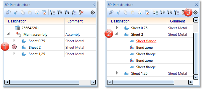
(1) Default setting Sheet Metal part collapsed, (2) Sheet Metal part expanded, (3) Settings for the ICN
Part attributes
Each sheet main part contains specific non-graphical information, such as quantity, item number, part name, weight or dimensions. This information, which are in HiCAD referred to as part attributes, are taken into account for BOM creation.
Use the Part attributes function (right-click on sheet main part in the ICN and choose Properties > Part attributes, please also see HiCAD Basics Help) to assign the attributes to the sheet main part. For value inputs in the Part attributes dialogue, no formulas, fractions, variables, units and spaces are allowed.
Some part attributes can be assigned automatically, e.g. the Sheet thickness or the Weight. For this, the parameters in the Configuration Editors need to be adapted accordingly.
- In the Configuration Editor at Sheet Metal > Default setting > Sheets BOM-relevant the BOM-relevance has been switched ON by default.
- The surface area of sheets is exactly calculated and entered for the Surface area attribute, accordingly. When the calculation is to take place can be determined at Sheet Metal > Default setting > Update BOM attributes. The default setting is Always.
- The selection of parts to be calculated can be preset in the Configuration Editor at System settings > Referencing:
Synchronize item numbers/part attributes when updating file (Never, Only for sub-parts, For main and sub-parts)
For main and sub-parts
- The weight calculation can also be preset in the Configuration Editor, at Modelling > Part properties:
Weight calculation: Do not auto-calculate, Only when itemising, Always
Only when itemising.
- If you want to assign different item numbers to sheet metal parts, you need to specify the setting in the Configuration Editor at Compatibility > Itemisation control > Settings for item number equality.
- For sheets, there is the additional coating attribute One-sided. If One-sided is activated, the sheet edge will be taken into account for surface calculation.
- Classification takes place via the attribute Usage. Via this classification you can, e.g. create usage-dependent workshop drawings or BOMs. The usages can be expanded and customized at any time with the Catalogue Editor. The usages are managed in the Factory standards catalogue. Further information on the Catalogue Editor can be found in the Online Help.
Semi-finished products
If you decide to use a semi-finished product  from the Catalogue Editor, the sheet thickness will not be requested, e.g. when creating a base sheet. The Sheet thickness and the Material will then be taken from the Catalogue Editor and applied to the base sheet.
The Article number is editable, even if the created sheet is generated from a semi-finished product from the catalogue. The catalogue column Designation is not necessarily linked to the article number in the part attributes; Designation can be linked to any part attribute (e.g. $01 Designation 1).
Semi-finished products can also be activated, deactivated or changed subsequently. To do this, double-click the Base sheet feature. The dialogue window for base sheet creation will be displayed. You can then activate or deactivate the Semi-finished product checkbox, or select a different semi-finished product by clicking the  icon. Confirm with OK.
The semi-finished product can also be activated directly via the feature log. Here, not only Yes and No are available but also the option Formula. The formula can consist of a variable that returns the result 1 (Yes) or 0 (No). If this variable is defined on the assembly, the subordinate sheets receive the variable YES_NO and can be provided with semi-finished products in one step. This procedure is important for automation solutions.
In the Catalogue Editor you can find the semi-finished products at Factory standards > Sheets. Here you can, for instance, select Aluminium sheets/plates, Stainless steel sheets/plates or Bulb plates.
For steel plates you can create your own tables in the Catalogue Editor at Factory standards > User-defined semi-finished products > User-defined plates. These tables are then also offered for selection in the function Steel Engineering > Plate, new > Rectangular plate.
Copy sheet
Copy flange or bend zone
If you copy the flange or bend zone of an edge sheet using the Copy to HiCAD clipboard  function (ICN function bar or right mouse button context menu), the entire sheet is always copied if the feature is active.
You can then use the Paste from HiCAD clipboard  function to insert the sheet as a new main or sub-part in the current drawing or in a new drawing.
Clone/Transform
If you select flanges and bend zones, the complete sheet metal part is always used for Transform and Clone actions.
![]() Please note:
Please note:
For flanges and bend zones without a feature, transforming and cloning individual parts is permitted.
Delete sheet
The Delete  function for Sheet Metal parts in the graphic can be called via
- the menu bar by selecting Drawing > Delete > Delete object,
- the ICN: Right-click the part you want to delete and choose Delete 3-D part, or
- right-click the part in the drawing area and choose Delete 3-D part.
The deleting of bend zones or flanges is only possible via the feature log. For sheets without feature, you can delete the flange or bend zone without further queries.
Blank
To obtain the blank (development) of the modelled Sheet Metal part, HiCAD offers you developments according to different calculation methods (allowance methods) that take the material-dependent length change of the workpiece during bending processes into account.
The bend lines, bend zones and bend angles can be displayed in the blank. Automatic part dimensioning enables a quick, user-defined variant of dimensioning.
HiCAD Sheet Metal can develop both sheet parts and 3-D parts and sheet parts from other systems.
The blank can be prepared for an NC programming system.
Weld seams
If you use the 3-D function Weld seam (3-D Standard > Standard Parts) for the welding on of a sheet metal main part, the weld seams will be determined for all sub-parts, and superfluous (double) powder marking lines will be removed. If a sub-part is selected for a welding, only the sub-part will be welded on.
Sectional views with coating lines
The coating lines in sectional views of Sheet metal parts can be processed with the functions of the context menu of coating lines (right-click the coating line to open the menu). You can
- change the coating line parameters
 ,
, - specify the distance (offset)
 of the coating line to the sheet, and
 - show or hide the coating lines
 .
.
Coating lines can be hidden or shown in the active view or in all sectional views. One distinguishes between coating lines on the inner side and the outer side.
If all coating lines have been hidden, the lines can be redisplayed again via the context menu for sheets: In the sectional view, right-click the sheet and choose Properties > Coating line .
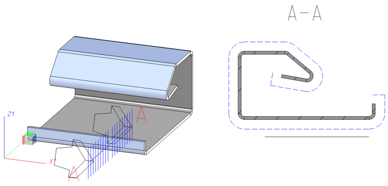
Coating line, outer side
The settings defined in the Configuration Editor at Drawing > Annotations > Coating line in sectional view are used to display the coating line.
