Edit Export Settings
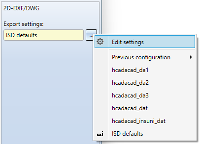
In the export dialogue for 2-D DX/DWG files you can call up an extended dialogue window for the export configuration via Export settings > ... > Edit settings to open an extended dialogue window for the export configuration.
The Export Settings 2-D DXF/DWG dialogue window consists of the following tabs:
![]() Please note:
Please note:
All options in the dialogue refer to both 2-D DXF and 2-D DWG export. If, for the sake of clarity, only "DXF" is written in the dialogue, for example in the tab designations, the DWG format is implicitly included.

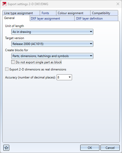
General
|
Unit of length |
These options can be used to control the unit in which the data is to be transferred to the DXF file. The header variable of the DXF file ($INSUNITS) is then set according to this unit. The default setting As in drawing transfers the data according to the HiCAD drawing unit. In addition to the selection options Millimetre, Centimetre, Decimetre, Metre, Inch and Foot that can be set as export unit, you also have the option here in the pull-down menu to set the transfer to Unitless. In this case, the data will be exported in HiCAD units, but the header variable will be set to "unitless" ($INSUNITS = 0). |
|
Target version DXF |
This option can be used to set whether the DXF file is to be exported in Release 2000 (AC1015) or Release 12 (AC1009) DXF format. By default, the DXF file is written in the version Release 2000 (AC1015). (This option replaces the former setting option "ACDXF" in the corresponding configuration file as of HiCAD 2023 Service Pack 1). |
|
Create blocks for |
Here you can determine with a corresponding puldown menu selection whether blocks for
are to be created. (This option replaces the former setting option "FIGBL" in the corresponding configuration file as of HiCAD 2023 Service Pack 2).
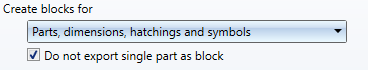
This setting may conflict with the "FIGLA" setting from the Compatibility tab: FIGLA 1 can only be used if no blocks are created for parts. If in the pull-down menu Create blocks for > Parts, dimensions, hatchings and symbols has been selected, then the checkbox option Do not export single part as block can also be activated below.
If only one part is exported, the active option controls that no BLOCK is created in the DXF file for this single part. (This option replaces the former setting option "FIGB1" in the corresponding configuration file as of HiCAD 2024). |
|
Export 2-D dimension as real dimensions |
This checkbox can be used to determine whether 2-D dimensions are to be transferred to the DXF file as dimension objects (DIMENSION), or only as geometries and texts. 3-D dimensions are always transferred as geometric dimensions. By default, 2-D dimensions are transferred as geometries and texts. (This option replaces the former setting option "BEMAS" in the corresponding configuration file as of HiCAD 2023 Service Pack 1). |
|
Accuracy (number of decimal places) |
Here you can specify how many decimal places are transferred to the DXF file. By default 8 decimal places are transferred. The maximum value for the number of decimal places is 14. (This option replaces the former setting option " NKST" in the corresponding configuration file as of HiCAD 2023 Service Pack 1). |
DXF layer assignment
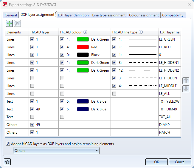
Using the table in this dialog tab, HiCAD Elements (lines, texts, other) can be assigned to corresponding DXF layers (DXF layer name) via their properties HiCAD layer, HiCAD colour and HiCAD line type.
Examples:
-
In the first line, all HiCAD elements of type Lines that have HiCAD layer "1", HiCAD colour "1" (dark green) and HiCAD line type "1" (solid) are assigned to DXF layer "LE_GREEN" in the DXF layer name column.
-
In the sixth row from the top, all Lines with HiCAD line type "3" (dashed) are assigned to the DXF layer "LE_HIDDEN" regardless of their layer and colour.
For HiCAD elements of the type Text the HiCAD line type is not relevant, for elements of the type Others HiCAD color and HiCAD line type are not relevant.
Others includes the elements Dimensions, Hatchings, Symbols and also Texts, if these have not been assigned before via Elements.
If the checkbox in a cell is activated, then the corresponding property of the element is taken into account.
The default properties of the DXF layer specified as DXF layer name can be configured via the DXF layer definition tab (see below).
At the bottom of the window, under this tab, you will find the pull-down menu item Adopt HiCAD layers as DXF layers and assign remaining elements.
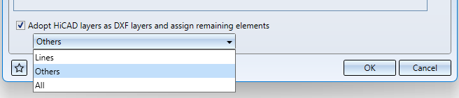
Here you can determine whether DXF layers should be created for unassigned elements (according to their HiCAD layer), and if so, for which type of elements:
-
Lines
-
Others (contains HiCAD texts)
-
All
The elements will then be assigned to the corresponding DXF layers.
If the checkbox is not activated, then all remaining elements will be assigned to DXF layer "0".
![]() Important:
Important:
The layer assignment is only performed if the keyword "FIGLA" in the Compatibility dialogue tab is set to 0 (this is the default setting for the keyword). If FIGLA is not 0, the options of this tab have no effect.
(This options dialogue replaces the former keyword settings "LAYER", "TXTLA" and "SONST" in the corresponding configuration file as of HiCAD 2023 Service Pack 2).
DXF layer definition
The table in this area can be used to configure the color (DXF color index), the line width and the line designation (DXF line type) for DXF layers. The DXF layers are transferred to the DXF file with their names and the selected properties (LAYER table).
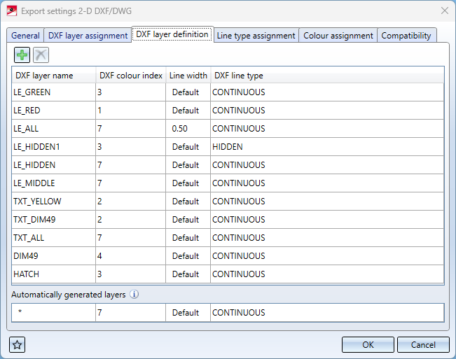
Independent of this configuration of the default values to the layers, DXF elements can also have their own DXF color, line width and line type.
For all other layers automatically generated during export, the properties of the bottom row Other layers are used.
![]() Important:
Important:
Each DXF line type listed there must also appear on the Line type assignment dialogue tab!
(As of HiCAD 2023 Service Pack 2, this option replaces the former keyword setting option "BYLAY" in the corresponding configuration file).
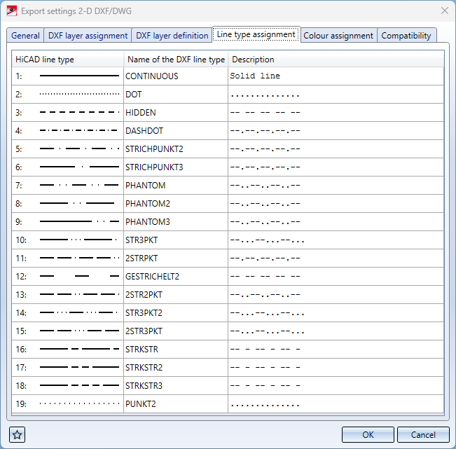
Line type assignment
On this tab, a DXF line type is assigned to each HiCAD line type. The DXF line type consists of a name (column Name of the DXF line type) and a Description.
(As of HiCAD 2023 Service Pack 2, this option replaces the former keyword setting option "LTDEF" in the corresponding configuration file).
Fonts
Via the configuration table in the Fonts tab, HiCAD fonts and DXF styles can be assigned to each other.
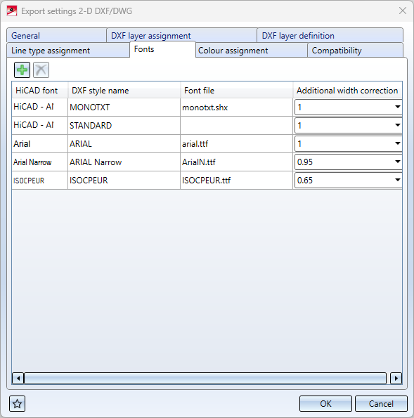
In the columns HiCAD font and DXF style name, corresponding fonts/styles are selected and assigned to each other line by line.
In the Font file column, the font file can be entered in addition to the DXF style name.
Via Additional width correction, a width correction of the HiCAD font can be carried out during export.
(As of HiCAD 2024, this option replaces the former keyword setting option "STYLE" in the corresponding configuration file).
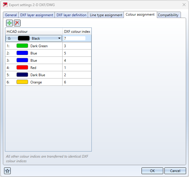
Colour assignment
The table in the Colour assignment tab contains an assignment of HiCAD colors to DXF color indices:
In the dialogue window, new rows can be added by clicking on  , or rows can be deleted by selecting them and clicking on
  .
.
If a HiCAD colour is not listed in this table, the assignment is as follows: The index by which the colour is represented in the DXF file corresponds to the original HiCAD colour index +1.
(This option replaces the former setting option "COLOR" in the corresponding configuration file as of HiCAD 2023 Service Pack 1).
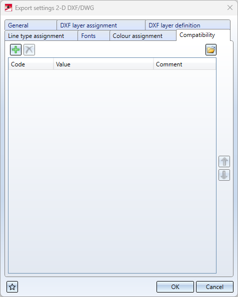
Compatibility
On the Compatibility tab of the export settings dialogue, you will see a list of all other set configuration Codes, their respective Values and a Comment line for them.
 Options available in earlier HiCAD versions via the configuration file acadhcad, which were not taken over into the settings dialogue within the scope of the conversion to a new export menu structure, can still be set via the compatibility tab for compatibility reasons, in order to continue to guarantee possible behaviour beyond the settings dialogue.
For the sake of clarity, however, these options are only displayed if they deviate from the default settings.
You have the possibility here to change settings based on configuration files which are not shown in the export settings interface.
You can change a Value by clicking in the corresponding field and changing it manually.
You can edit an entire row including the Code and Comment by selecting it and clicking on the symbol in the upper left corner.
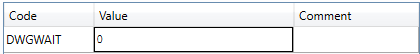
As an example, the following image shows the key DWGWAIT with the value "0" (the preset value for DWGWAIT in the default settings is "1").
You can load the configurations from older configuration files (hcadacad.dat) by clicking on the  symbol at the bottom of the window and selecting a corresponding one in the following selection dialogue. If the file has been successfully transferred, you will receive a system message.
Clicking the  symbol at the bottom left opens the Favourites menu.

Create 2-D DXF/DWG File • Keywords • 2-D DXF/DWG Settings • 2-D Interfaces