Sheet Metal > New > Pipes + Vessels 
Sheet Metal > New > Pipe.. .> Sub-part
The Pipes + Vessels function creates a hollow or solid part as a main or sub-part. After calling the function, a dialogue window opens with six different pipe types that can be created by entering values. Each type can be created either as a sheet or as a solid. The preview automatically adapts to the values entered.
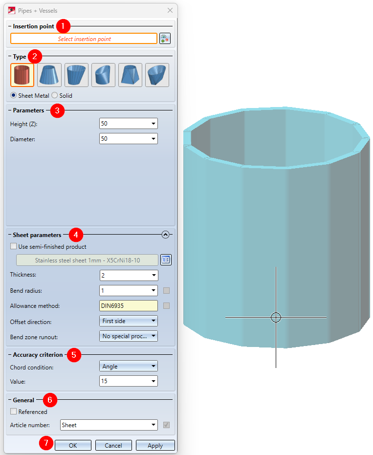

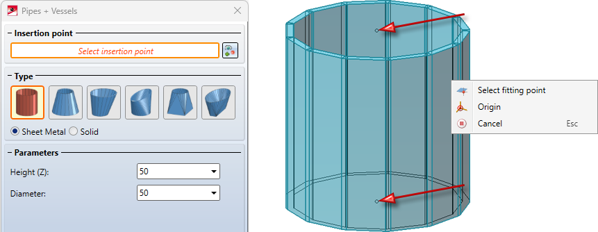
Insertion point
When the dialogue window opens, the Select insertion point option is activated. To change this subsequently, you can click on the  icon. Right-click to open a menu in which the first option is Select fitting point. Here you can choose between the two available fitting points to select the desired point for insertion. The second option in this menu is the origin. This sets the sheet metal part/solid to the Origin in the coordinate system.
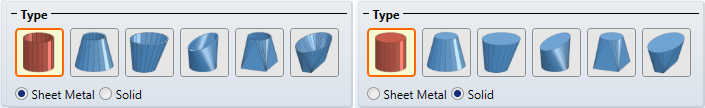
Type
Six different creation options are listed in the Type area. The currently selected type is highlighted in red, e.g.  you have the option of creating the types either as a Sheet Metal part or as a Solid. The icons in the dialogue window change depending on the selection between Sheet and Solid.
The following types are available:
|
|
|
|
|||
|
|
|
|


Parameters
Specify the values for the selected Type in the Parameters area. The input fields depend on the selection. The preview of the pipe/vessel is updated after confirming the value entry with ENTER or RETURN. The parameters for the different types are explained in detail in separate topics.
Sheet parameters
The Sheet parameters are only active if you have selected Sheet Metal. In this section, the Use semi-finished product checkbox can be selected. A material can then be selected from the catalogue using the  icon. This defines the thickness of the sheet, which can only be changed via the catalogue.
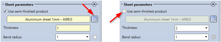
However, if the Use semi-finished product checkbox is deactivated, a Thickness must be selected manually. The Bend radius can be freely selected. The bend radius can also be taken from the catalogue using the checkbox next to the input field.
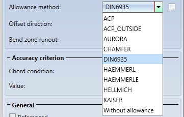
In order to obtain the development of the modelled Sheet Metal part, HiCAD offers you developments according to various calculation methods (Allowance methods), which take into account the material-dependent change in length of the workpiece that occurs during bending. HiCAD also offers the allowance methods commonly used in practice. A specific calculation method is represented by a system file. These files are prepared as examples, but in practice every user will store one or more methods in this way. Activate the From semi-finished product  checkbox next to the Allowance method field if you want to transfer the file from the Catalogue Editor.
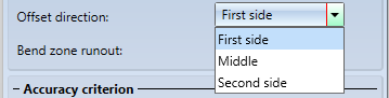
For the Offset direction, specify the side to which the sheet thickness is to be generated. First side means that the diameter is measured on the outside and the sheet thickness is created on the inside. In the Middle, the sheet thickness is generated equally on both sides. With the Second side, the inside diameter is measured and the sheet thickness is generated on the outside.
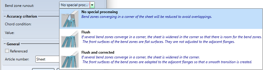
The Bend zone runout offers the final setting option for the Sheet parameters and allows you to choose from three different options.
Accuracy criterion
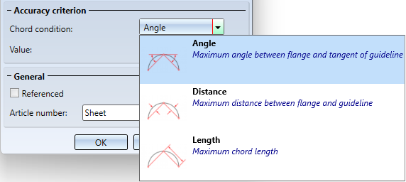
The Chord condition is the first option available in the Accuracy criterion section. You can choose between three different conditions: Angle, Distance and Length. As a second option, a Value can be entered to increase the accuracy.
Chord condition - Examples
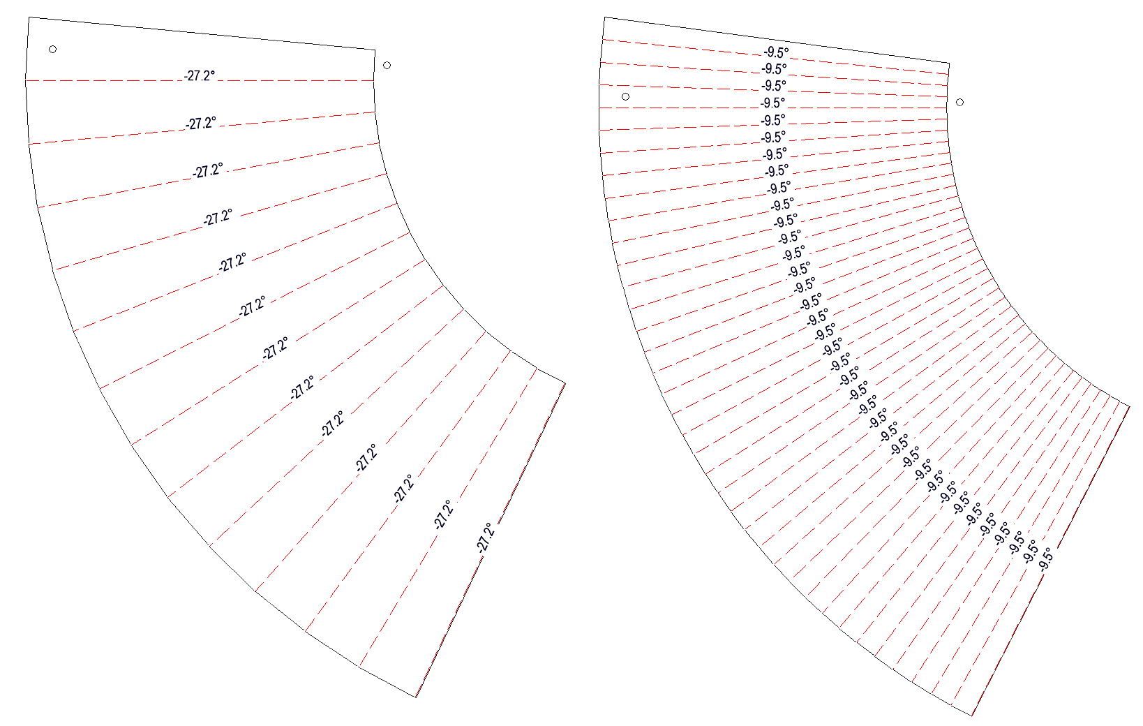
Angle - Example: The first development has been created with the Value 15 and the second development with the Value 5. This Value specifies the maximum Angle between the flange and the tangent of the guideline.
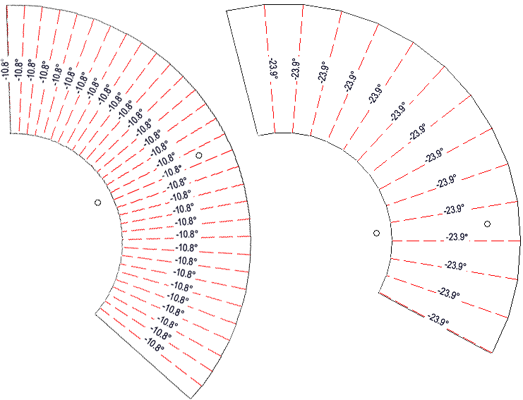
Distance - Example: The first development has been created with the Value 0.2 and the second development has been created with the Value 1. This Value specifies the maximum Distance between the flange and the guideline.
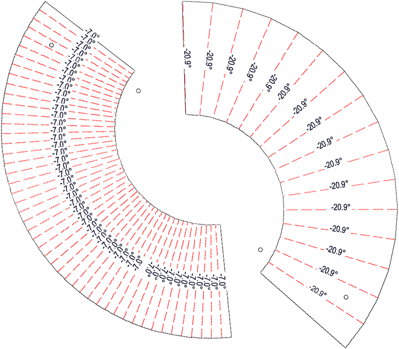
Length - Example: The first development has the Value 5 and the second development the Value 15. This Value describes the maximum chord length.
General
Click on the Referenced checkbox if the part is to be saved as referenced. A frequently used part should be saved as referenced. The part is then also saved as an individual part at the end of the function sequence and is not permanently integrated into the drawing. If the individual part is changed you can update the part in the drawing.
If you have selected Sheet Metal and activated the Use semi-finished product checkbox, an Article number is automatically generated. The article number is based on the material and thickness. You can change this by deactivating the checkbox next to the input field.
Apply/discard inputs
There are three buttons in the dialogue window. The Apply button positions the part at the selected insertion point and a new part can be created. If you confirm with the OK button, the part will be created and the dialogue window closes. Clicking the Cancel button or pressing the middle mouse button ends the function, and the dialogue window will close without a part being created.
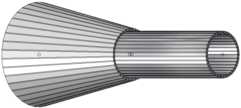
Example:

Create Base Sheet (3-D SE) • Overview of Functions (3-D SE) • General Notes on Sheet Metal Processing (3-D SE)