Information - Other Functions

|
Information, 3-D point coordinates Shows the coordinates of any 3-D points. Please note the following: |
||||||||||||||||
|
|
Information, 3-D Graphical elements and radii Displays information about arbitrary 3-D line elements and radii. These can be, for example:
Clicking
|
||||||||||||||||

|
Displays information about 3-D surfaces. |
||||||||||||||||
|
|
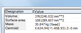
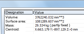
Information 3-D part, Surface area, Volume, Mass* Detects the surface area, the volume and the mass of the active part. Please note that the mass depends on the material assigned to the part.
Clicking
|
||||||||||||||||

|
Information, Text Displays the text attributes of the identified text. Clicking
|


|
|
Finds the in the current drawing 3-D parts with identical geometry. |
|
|
Checks whether parts in the drawing collide with each other. Clicking |
|
|
Colour-marks referenced 3-D parts of the drawing. Clicking |
|
|
Manages user-specific variables. |
|
|
The Design Checker is a tool that enables you to increase the quality of your drawings and reduce costs and time through an early detection of errors in the design. You can auto-check your drawings for their compliance with specific construction guidelines; it detects, for example, invalid features, incorrect bolting sets, dummy parts, and much more. If any errors are detected, HiCAD issues an appropriate message and suggests corrections. Clicking |
|
|
With this function you can find parts and assemblies that have a particularly negative influence on the performance of the current model drawing. This makes it easier to optimise the corresponding parts/assemblies for faster work. |
|
|
Use this function to check whether a cylindrical pin that was inserted for the connection of two parts has the required stability to withstand a specific force. The function calculates the shear force in the shear joint, and the required minimum diameter of the pin. |
|
|
Use this function to check whether a radial pin that was inserted for the connection of a shaft and a hub has the required stability. The function calculates the minimum diameter of the pin, the shear stress in the pin, the torsional stress and the tensioning pressure in the shaft, and the tensioning pressure in the hub. |


Graphical elements and radii (3-D)
Information > 3-D, Further > 3-D GE and radii 
This function displays information on arbitrary 3-D graphical elements and radii.
Identify the graphical element.
The following information is output:
- Line
Start and end point, length - Circle,
circular arc
Start and end point or closed, length, radius - Ellipse,
ellipse arc
Start and end point or closed, midpoint, length, semi-axes. - Section
curves
Start and end point, length, possibly FFS data - Freeform
surface edges
Type, control points, order, precision
Information, 3-D Surface
Information > 3-D, Further > 3-D Surface
This function displays information about 3-D surfaces. These are: Surface area, centroid and normal vector. Inner cycles are taken into account as well. In this case, the number of surface cycles is output additionally.
Information, 3-D Sketch
Information > 3-D, Further > Line > Sketch, Open polylines 
Use this function to check whether a sketch is closed. In addition, length and surface area of the sketch and, if desired, other calculation data are detected.
- HiCAD checks whether the active sketch is closed and issues a corresponding message.
- Close the message window with OK. For non-closed sketches the function will be ended.
- For closed sketches, length and surface area will be detected. If you want the program to display further calculation data, e.g. moments of inertia, moments of resistance, centroid coordinates etc, click Yes.
In addition, the Sketch, Self-intersection  function is available, that enables you to check sketches for self-intersections. Detected self-intersections are marked with a small circle.
Information 3-D part, Mass moment of inertia, complete
Information 3-D part, Mass moment of inertia, complete 
This function determines the mass moment of inertia of the active 3-D part. The mass moment of inertia is the measure of a rotating body's resistance to a change in speed.
The concept of the moment of inertia plays an important role in rotational movements of bodies in physics and technology. Examples are gyroscopic phenomena, spectroscopy as well as all rotating parts in engines.
The function Information 3-D part, Mass moment of inertia in relation to axis  works in a largely similar way, you need however define the axis of the moment of inertia.
Information, Bounding box
Information, Bounding box 
This function displays the so-called bounding box of the active part. This is the smallest cuboid that completely encloses the part. Identify the view in which you want the bounding box to be displayed.
The light-cube coordinates are stored as system variables ZMAX, ZMAY, ZMAZ und ZMINX, ZMINY, ZMINZ in the Variables Memory.
Identical part search
Information > 3-D, Further > Identic.
Use this function to find in the current drawing 3-D parts with identical geometry.
- Find part in drawing
HiCAD finds all parts in the drawing whose geometries coincides with the selected part. The found parts are highlighted in the drawing, and a message informing you about the number of identical parts is displayed.
- Compare two parts
Use this function to check whether the geometry of two parts is identical. Identify the two parts. If the geometries of the parts coincide, they are highlighted.
Collision check
Information > 3-D, Further > Coll.
This function enables you to check whether the sub-parts of the active part collide. If the active, superordinate part is a solid, HioCAD will also check whether the active part itself collides with one of its sub-parts. Self-intersections of the active part will not be indicated here.
|
|
2 parts Indicates the collision of two arbitrary parts. After choosing the function, select the two parts. Collisions of a sub-part of the first identified part and a sub-part of the second identified part will be shown. Collisions of two sub-parts which are both located beneath one of the selected parts will not be indicated. |

|
All parts Indicates collisions of all parts of a drawing. |
|
|
Selected parts Indicates collisions of all parts of the current part list, i.e. all currently marked parts. Before calling this function, select the required parts, either in the drawing or in the ICN. In contrast to the 2 parts option, the collisions of all sub-parts of the superordinate parts contained in the part list will be indicated individually here. |


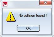
If no collision is found, a corresponding message is displayed:
If a collision is found, it will be highlighted if desired, and you can decide whether you want to continue the check.
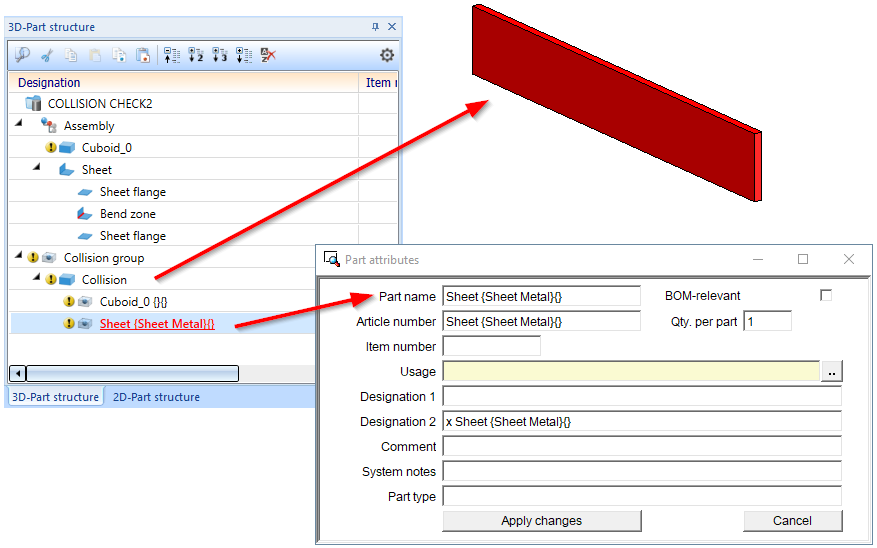
For each collision, a collision part called Collision of the type Solid is created, with the geometry of the collision. This contains the part "copies" of the two parts causing the collision. These copies are dummy parts that have no geometry and only limited part attributes. These two dummy parts serve with the names of the parts causing the collision. This serves to clarify the cause of the collision more quickly, since the collision part may be very small and often almost invisible visually. As a rule, the name of the source part displayed in the ICN, including article number and comment, is used as the part name and article number of these dummy parts. An exception are collision parts that are not "real" parts. In this case, the name of the superordinate part is used for the dummy part. All collision parts are combined under the name Collision group. This applies to threads, sheet metal flanges, bend zones and sub-parts of series beams and profiles.
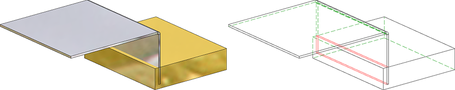
Example
In the image below, the sheet metal part - or more precisely the flange - collides with the cuboid.
Select active part
Information > 3-D, Further> Select 
The Select active part function highlights the active part in your drawing.
In the pull-down menu  of the function you will find other functions for marking referenced parts.
|
|
Individually Checks whether a particular part is referenced. |
|
|
Identical parts Finds and highlights all identical parts of a referenced part. |
|
|
All parts Finds and highlights all referenced parts of the drawing. |


