AutoGenerate Isometry - Specify Actions
Plant Engineering > Isometry / Pipe Spool Drawing > AutoGenerate isometry 
Plant Engineering > Isometry / Pipe Spool Drawing > Generate pipe spool drawing 
Isometry + pipe spool drawing > Create > AutoGenerate isometry 
On the right hand side of the Plant Engineering Isometry dialogue window, you can define various options and actions for the isometry documents to be created:
- Drawing frame and Scale
- Selection of elements / actions
- Further options for isometries
- Further options for pipe spool drawings
The settings apply to the pipeline which is marked on the left hand side of the list. If you want to apply the settings for one pipeline to all other selected pipelines, click the Apply to all pipelines button.
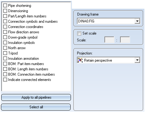

Drawing frame and Scale
For the isometry or pipe spool drawing of pipelines you can use different drawing frames. Select the desired frame from the listbox. If you do not want to use a drawing frame, leave the corresponding input field empty.
When creating a Plant Engineering isometry you can preset the scale for the isometry if required. If you do not preset the scale, HiCAD determines the scale automatically. After creating an isometry, the last calculated scale is saved and can be adapted before re-creating the isometry. Once set, the scale remains the same until it is deactivated again (and a new isometry is created while the scale is deactivated).
 Please note:
- You can individually determine the area of the drawing frame used by the isometry. This enables e.g. the creation of asymmetrical filling margins etc.
- The specified scale refers to the scale for the isometric drawing. Please note that the isometric drawing represents a projection, causing pipe lengths to appear slightly compressed in the isometry compared with 2-D lengths, e.g. in drawing frames. The compression factor is approx. 82% or, to be more precise, cos(asin(tan(30°)), for distances running parallel to the coordinate system.
- If the pipeline shortening option is active, the concept of a fixed scale will become insignificant. Of course, the isometry will continue to possess a "pro forma" drawing scale, which can also be overwritten manually. In such cases, however, the drawing scale is to be considered as a mere scaling factor.
- If you work with HELiOS and do not use a document master, the isometry or pipe spool drawing will fill the title block of the drawing frame with drawing attributes and part attributes, using the schrife_anl_iso_spool.dat file in the sys directory of the HiCAD Installation. This file determines which attributes will be assigned to the text keys in the drawing frame.
Selection of elements / actions
You can specify via activation of the appropriate checkboxes which of the actions below you want to be executed on the pipelines.
Click the Select all button to activate all actions in one step.
- Pipe shortening(only for isometries)
In the isometry, a true-to-scale representation of the individual pipe parts of a pipeline is usually not important. This fact can be used to provide extra space for symbols (flow direction arrows, or insulations symbols...) through pipe shortening, or to achieve a well-arranged, optically appealing representation.
If this option is active, the pipeline will be shown in a non-scale representation, in order to provide a well-structured view of the drawing. The straight pipes will be shortened (or lengthened) in such a way that all entries will have enough space. The settings specified on the Pipe shortening tab will be considered for the calculation of the length change.
In older HiCAD versions, loops in pipelines were never considered for pipe shortenings. This behaviour has been changed with HiCAD 2014 SP2, i.e. loops can also be considered. If you prefer to use the old procedure, start the Configuration Editor, select Plant Engineering > Isometry and Pipe spool drawing, and deactivate the Apply pipe shortening to pipeline loops checkbox.

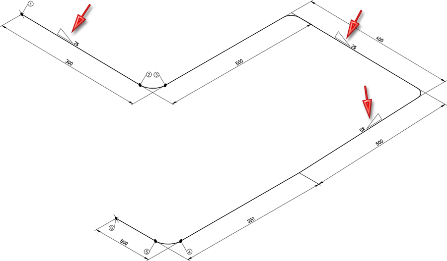
- Dimensioning
Generates dimensioning for guidelines, i.e. composite edges, belonging to the active pipeline, whereby a dimension line with appropriate dimension is generated fr each edge. Let us assume that the name of the pipeline is RBL0001, the guideline parts Q_ANL_001, Q_ANL_002, Q_ANL_003 etc. are dimensioned. HiCAD permits a gap of up to four increments between guideline numbers. Automatic dimensioning works in this way if, for example, only guideline parts Q_ANL_003, Q_ANL_008 and Q_ANL_010 exist.
HiCAD creates a new sub-part of the pipelines main part, i.e. RBL0001, for dimensioning. The sub-parts SDR_ANL and MSL_ANL RBM_ANL are in turn created. The sub-parts Y_ANL_nnn containing rise triangles, are attached to the sub-part SDR_ANL. Rise triangles are consecutively numbered, i.e. nnn = 001, 002, 003 etc. Hi-CAD assigns any existing projection lines to MSL_ANL, e.g. automatically created projection lines for circular arcs.
Please note:
Guidelines are only insertion aids for layout plans and do not influence the dimensioning in isometric drawings; pipelines that begin or end with an elbow or contain a 180° bend are fully dimensioned in isometric drawings.
- Part item numbers
HiCAD automatically assigns part item numbers in logical sequence according to given settings, and outputs them as described in the chapters Text/Lines and Text objects. - Weld seam item numbers
If it has nor already been carried out, HiCAD first executes the Welded connection info function, and then assigns welded connection item numbers in logical sequence according to given settings and outputs them graphically as described in the chapters Text/Lines and Text objects. - Connection coordinates
HiCAD creates and outputs text objects graphically, as described in the chapters Text/Lines and Text objects. - Flow direction arrows (only for isometry)
Initially, the direction of flow is arbitrary, whereby only logical combinations are applied to branches. HiCAD creates and automatically positions and aligns flow-direction arrows according to the presettings, as described in the Setting -Symbols topic. You can call the Set flow direction function afterwards and change the flow direction interactively.
- Down-grade symbols (only for isometry)
Down-grade symbols can only be set on straight pipes and straight sections of bent pipes. The parameters for the automatic creation of down-grade symbols can be specified in the Symbols tab of the Isometry Settings dialogue window. Further settings for down-grade symbols can be found in the Configuration Editor, at Plant Engineering > Isometry and Pipe spool drawing.
- Insulation symbols
It is now possible to set symbols for insulation, heating and cooling in the isometry automatically. Like, for instance, the flow direction symbol, these symbols are also aligned at the centre line of a straight pipe and taken from the symbol table (\sys\symzab.sza). - North arrow
North arrows are only inserted in isometric drawings if the appropriate pre-determination exists. The north arrow will be created, automatically placed and aligned according to the pre-settings, as described in the Setting -Symbols topic. The position of the arrow is determined by the settings in the Configuration Editor, at ...> Plant Engineering > Isometry and Pipe spool drawing.
- Tripod for orientation
A “tripod” indicating the orientations of the coordinate system (3) can be inserted in isometric drawings. The tripod will be created, automatically placed and aligned according to the pre-settings, as described in the Setting -Symbols topic. The scaling factor is determined by the settings in the Configuration Editor, at ... > Plant Engineering > Isometry and Pipe spool drawing.
- Insulation annotation
If this checkbox is active, insulations in the isometry are annotated. - Bills of Materials
This action allows a direct integration of BOMs into the isometry document. You have the option to display an overview of welded connections in BOMs. For this to happen, go to Plant Engineering > Bills of Materials in the Configuration Editor and activate the checkbox of the parameter Supplement BOMs with an overview of welded connections.
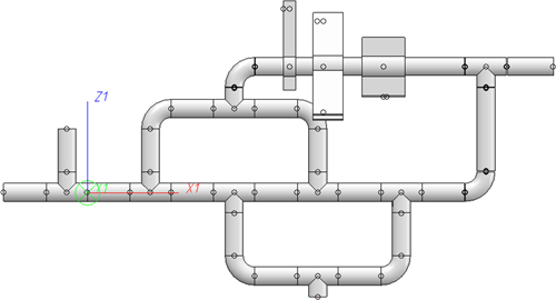
- Indicate connected elements (only for isometries)
A pipeline isometry provides a symbolic representation of the composition of a pipeline. In most cases, this pipeline is part of a larger plant in the layout plan. Within this layout plan there are other pipelines or components that are adjacent to the pipeline viewed in the isometry. Portions of these adjacent pipelines and components can be indicated to provide the observer with additional information on the pipeline environment. If this checkbox is active, the presence of connected pipelines will be indicated, e.g. by means of dashed representations. You can specify the exact representation on the Symbols tab in the Isometry Settings. The setting can be specified separately for pipes and components. In addition, you can specify there whether pipe clamps of other pipelines (multi-pipe clamps) are to be indicated or not.
The image below shows a pipeline to which a vessel, a pump and another pipeline have been connected.
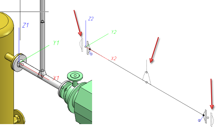
When indicated elements are used, another level called ~ConnectedElements will be added to the 3-D part structure of the pipeline isometry. Beneath this item you will find a sub-item called ~Component for each indicated component, and a sub-item with the name of the indicated pipeline.
Structure of the above example

If you want to exclude any indicated parts from the representation, you have the option to remove them by rendering them invisible: Right-click the item in the ICN and choose the corresponding function beneath Visualisation.
You can only indicate such parts that also exist in the original drawing. This is important in cases where a pipeline isometry is the original drawing from which another isometry has been derived. One concrete use case would be an isometry that has been spread over several sheets. Here, it would not be possible to perform a subsequent indication of elements which do not exist in the original drawing. If you spread an isometry over several sheets using the Specify division option, the corresponding partial pipeline isometries will be added to the elements to be indicated and will then also appear in the 3-D part structure beneath ~ConnectedElements.
In this context, please also read the notes on the Representation of Multi-Pipe Clamps.
Further options for isometries
A Projection can be chosen for each individual pipeline. When you do so, the chosen projection of the pipeline will be shown in the HiCAD drawing area.
To assign a projection to a pipeline, proceed as follows:
- Click the desired row in the pipelines list.
- Select the desired entry from the Projection listbox.
With regard to the selected projection please note the following:
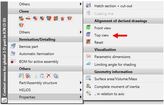
The functions beneath Alignment of derived drawings in the context menu of assemblies allow you to determine whether the active view is to be interpreted as  Front view or
 Top view of derived drawings. This means that a View CS will be defined for the front view or top view of the corresponding assembly.
These functions can also be applied to pipelines. In the ICN, right-click on the pipeline, open the Properties sub-menu and choose the desired function.
Isometry and pipe spool drawing will then consider the view coordinate system that was defined in this way:
- In the pipe spool drawing, all views will be created with regard to the defined view coordinate system.
- This also applies to the isometry - with the exception of the Retain perspective projection. It serves the purpose of creating an isometry in the view coordinate system of the currently active view; therefore the selected alignment has no effect here.
- The Set reference CS for isometry
 function that determines in which coordinate system the coordinates in dimension tags are to be calculated remains unaffected by this.
To Reset the selected alignment, choose the same -named function in the context menu of the pipeline.
The alignment chosen for a pipeline can be marked accordingly in the model drawing.
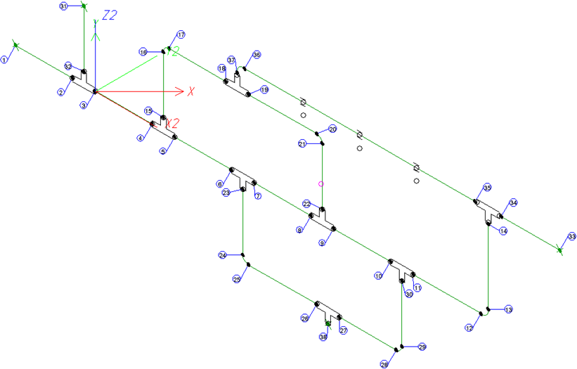
Example:
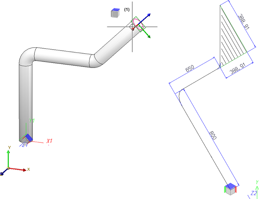
The image below shows a pipeline for which no view alignment has been set. For the isometry, the Isometric projection 1 has been chosen.

If you now open the context menu with a right-click, choose Properties > Alignment of derived drawings > Front view, and select the marked surface (1) in the image below, this will affect the isometry:

In the next image, Properties > Alignment of derived drawings > Top view has been chosen, and then the marked surface (1):
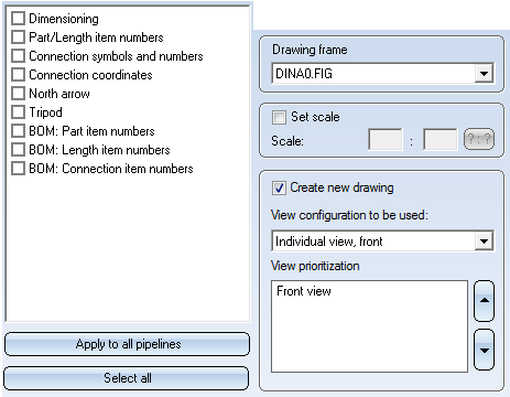
Further options for pipe spool drawings
Create new drawing
If this checkbox is active (default) a separate drawing file will be created for the pipe spool drawing. If the checkbox is inactive, the pipe spool drawing will be generated in a new sheet area of the current drawing. You can preset in the Configuration Editor whether the checkbox should be active or inactive by default: Select Plant Engineering > Isometry and Pipe spool drawing, and activate or deactivate the Always generate pipe spool drawing in new drawing file checkbox.
View configuration to be used / View prioritization
In the Configuration Editor (ISDConfigEditor.exe) you can define view configurations for pipe spool drawings. These can then be selected from a list box. The views belonging to a configuration can be selected from a listbox. The views belonging to the selected configuration are listed beneath View prioritization. Each
You can specify the following parameters for a view:
- the unambiguous number for identification
The numbers assigned to the supplied configurations should not be changed! - a view configuration name
This name will be shown in the pipe spool drawing dialogue. - the projection type
- the representation type
- the positioning of the view
Here you specify whether the view should be positioned relative to another view, or if it is an "anchor view" used as an orientation for other views. - the reference view used as orientation for the positioning of views
Here you must enter the unambiguous number of the reference view. - the alignment along the common edge with the reference view
- the distance to the reference view in millimetres
The view configurations themselves have the following properties:
- an unambiguous number
This number will be used to show you which configuration was selected when the dialogue was called last. - a name
This name will be shown in the pipe spool drawing dialogue. - the item number
This number determines the order of the configurations in the list of the pipe spool drawing dialogue. Here you can, for example, assign the lowest number to the most frequently used configuration, to make it the default setting. - Visibility in selection list
For each view configuration you can specify, by activating the corresponding checkbox, whether it should be available in the dialogue during pipe spool drawing generation.
If there are several views you have the option to change their order using the  and
and  buttons next to the list. The uppermost view is the main view of the pipe spool drawing. The main view contains all pipe spool drawing elements, such as dimensioning and item number tags. If any item number tags in the main view belong to hidden parts, they will be passed on to the next view, taking the order of the other views into account.
The item number tags are distributed according to the following logic:
All item number tags the base points of which are hidden by a part, will be assigned to the next view. If some base points are still covered in this next view, they will be assigned to the subsequent view etc.
This procedure will be repeated until all item number tags could either be finally assigned to a view, or until all available views have been tried out. In the latter case, all remaining item number tags will then be assigned to the main view.
Example:
In the image below an inserted pipe points to the back and is therefore be hidden (1) if the construction is viewed from the front (1). Its item number tag has therefore been assigned to the second view (2):
Templates for own view configurations in pipe spool drawing
If you want to use your own view configuration, use the following, predefined templates in the Configuration Editor, and derive new view configurations from them. You can then configure these derived templates according to your requirements, e.g. you can add new views.

Please note:
- The base points of various item number tags will be set as follows:
- Item number tags for parts and lengths are attached to the outside of pipe parts if possible.
- Item number tags for connections are attached at the intersection surfaces of pipelines if possible.
- Item number tags for connecting points are attached exactly to the connecting points.


AutoGenerate Isometry (Iso)• Isometry and Pipe Spool Drawing (PE) • Isometry and Pipe Spool Drawing Functions for the Layout Plan (PE)