Generate Isometry / Pipe Spool Drawing
Plant Engineering > Isometry / Pipe Spool Drawing > AutoGenerate drawing (Iso) 
Plant Engineering > Isometry / Pipe Spool Drawing > Generate pipe spool drawing 
Isometry + pipe spool drawing > Create > AutoGenerate drawing (Iso) 
These functions enables an automatic generation of isometries and pipe spool drawings. When you select one of the isometry function, HiCAD displays the Plant Engineering Isometry dialogue window.
Please note:
As of HiCAD 2015 SP2 the drawing frames offered for isometries and pipe spool drawings are no longer offered via the dinframes.ddt file in the makroanl directory, but via the Configuration Editor, at Plant Engineering > Isometry and Pipe spool drawing > Drawing frames. When you call the functions for automatic isometry generation and pipe spool drawing generation, these settings will be checked. If adjustments are required, the dialogue window may therefore not appear immediately, but an appropriate message will be displayed. More information can be found further down the page.
After activating the pipe spool drawing generation, HiCAD will prompt you to select the part chains for the pipe spool drawing. Then, identify a part of the desired pipeline. HiCAD will automatically highlight the complete part chains to which the part belongs. You can then select further part chains. You have also the option to right-click and switch to the Part selection mode. In this mode you can add part to the selection, or remove parts from it. Right-click again to get back to Part chain selection mode.
To end part selection and start pipe spool drawing generation, press the middle mouse button. The Pipe spool drawing dialogue will be displayed.
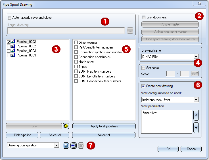
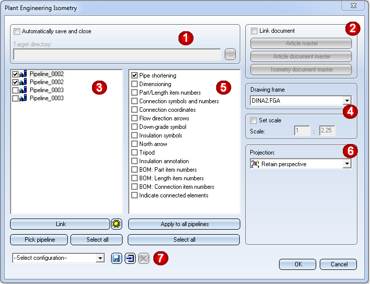
Specify the required settings:
- Definition of 'Save' options (1)
- Reference isometry / pipe spool drawings and manage via database (2)
- Select pipeline (3)
- Specify drawing frame and scale (4)
- Select isometry / pipe spool drawing elements and actions (5)
- Further options for the isometry(6)
- Further options for the pipe spool drawing (6)
- Working with configurations
Click OK, to start the generation of the isometry / pipe spool drawing. HiCAD will first check whether a HELiOS data record has been assigned to all connection types. If this is not the case, the references to data record attributes will be ignored. This may in particular lead to incomplete weld seam lists.
In such cases, a corresponding message will be displayed:
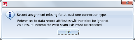
Click OK to continue with the generation of the isometry.
Define missing assignments on the Connections tab of the Isometry: Settings  dialogue window.
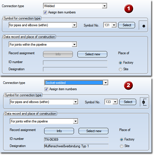
Connection type - Assigning of Data record and place of construction: (1) no assignment yet, (2) with assignment
 Please note:
- Before the isometry settings dialogue window is displayed, HiCAD carries out a structure check of the appropriate pipelines. Faulty pipelines are displayed and removed from the selection list for the isometry. By this means, isometries of intact drawings can still be created.
- Part list, length list and weld seam list are automatically created. If they are not visible, you need to activate View all.
- The settings in the Configuration Editor, at ...> Plant Engineering > Isometry will be considered for the isometry / pipe spool drawing generation. Please note that links between isometry/pipe spooll drawing and layout plan will only be created if the corresponding option has been activated in the Configuration Editor (...Plant Engineering > Isometry > Create document links
 .
. - The presettings in the dialogue window will be influenced by the settings in the Configuration Editor, at ...> Plant Engineering > Isometry.
- If you want the Pipe spool drawing window to be displayed immediately when calling the Auto-generate drawing function, change the setting in the Configuration Editor accordingly: Select Plant Engineering > Isometry and pipe spool drawing and deactivate the Allow part selection before displaying pipe spool drawing dialogue checkbox. The Pipe spool drawing window will then be displayed immediately after selecting the Auto-generate drawing function. If a pipeline was active when the function was called, this pipeline will be selected for the dialogue window. All parts of the pipeline will then be used for pipe spool drawing generation.
- If you have already selected several parts in the current Plant Engineering drawing, the function can also be activated with a right-click on the selection. You can then choose between the following options:
- From current part selection
Immediately displays the Pipe spool drawing dialogue window. - From new part selection
Allows you to modify your selection. - When an isometry or pipe spool drawing is loaded, the Isometry + Pipe spool drawing tab will be activated automatically. Use the Auto-generate drawing function to open the Plant Engineering Isometry or Pipe spool drawing dialogue window. These dialogue windows contain the setting options for the active isometry or pipe spool drawing.
- When aligning part and connection body symbols in isometries, entire pipe sections will be considered, in order to achieve a consistent aligning.
- Collisions of dimensionings and rise triangles in generated isometries will be avoided where possible.
 Important:
As of HiCAD 2015 SP2 you specify via the Configuration Editor, at Plant Engineering > Isometry and Pipe spool drawing > Drawing frames which drawing frames are to be offered for selection. Before HiCAD 2015 SP2 this was specified in the dinframes.ddt file in the makroanl directory.
When you call the isometry or pipe spool drawing dialogue, HiCAD will check whether the MAKROANL directory of the HiCAD installation contains a file called dinframes.ddt (drawing frame settings file in versions before HiCAD 2015 SP2). If this is the case, its contents will be read and compared to the list from the ISD Configuration Editor.
- If the contents are identical, the isometry/pipe spool drawing dialogue will be continued as usual.
- If the contents are different, the following message appears:
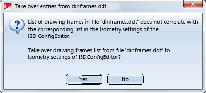
Clicking Yes copies the list from the dinframes.ddt file to the settings of the ISD Configuration Editor. Click No to skip the copying. If you definitely want no copying, delete the dinframes.ddt file.
The taking over of the list is only successful if a corresponding entry exists in the ISD Configuration Editor at Drawing frames. If this is not the case, e.g. because an older configuration is being used after an update, the following message appears:
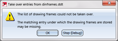
In no case, however, an entry in the Configuration Editor will be created.


Isometry and Pipe Spool Drawing (PE/Iso) • Isometry and Pipe Spool Drawing Functions for the Layout Plan (PE) • Plant Engineering Functions • Settings in the Configuration Editor (PE/Iso)