Plant Engineering > Isometry/Pipe Spool Drawing > Isom...
Isometry+Pipe Spool Drawing > Create > New 
Multi-pipe clamps comprise more that one pipe part. The Plant Engineering Isometry represents a multi-pipe clamp by replicating the symbolic representation of the clamp at each of its connecting points, and joining all these connecting points by a dashed line.
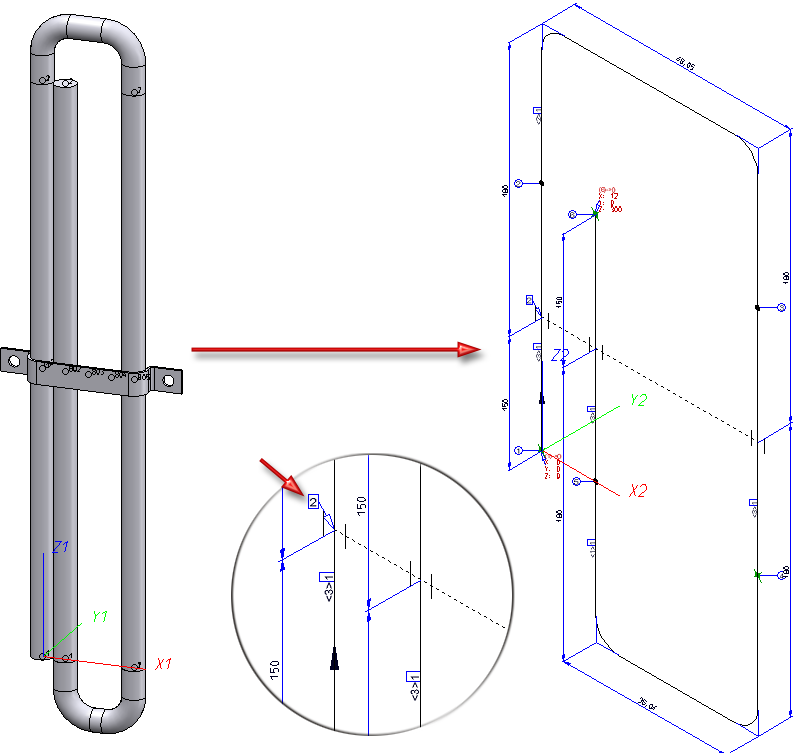
Pipeline with multi-pipe clamp and associated isometry
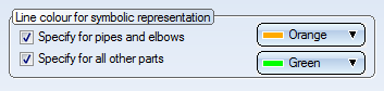
The item number tag on the clamp is only created at the lowest connecting point used (in the image above this is the tag with item number "2"). While the colour of the clamp symbol copies depends on the original symbol, the colour of the connecting line can be specified on the Part insertion tab of the Plant Engineering Settings dialogue window: Beneath Line colour for symbolic representation, activate the Specify for all other parts checkbox and choose a colour.
The structure of the clamp symbol is represented in the ICN as follows:
- The symbol to which the item number tag points is located in the ~Symbol part.
- The two other symbol copies are located in the parts ~Aux0001 and ~Aux0002. The connecting line is located in the ~Aux0100 part.
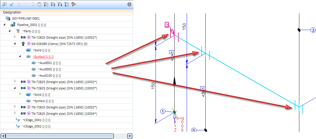
ICN structure of clamp symbol
Multi-pipe clamps are also supported as adjacent parts, meaning that in the layout plan the clamp is assigned to a different pipeline than the one for which the Plant Engineering isometry was generated. In this case the clamp is represented by a dashed line, analogous to the representation of other adjacent parts:
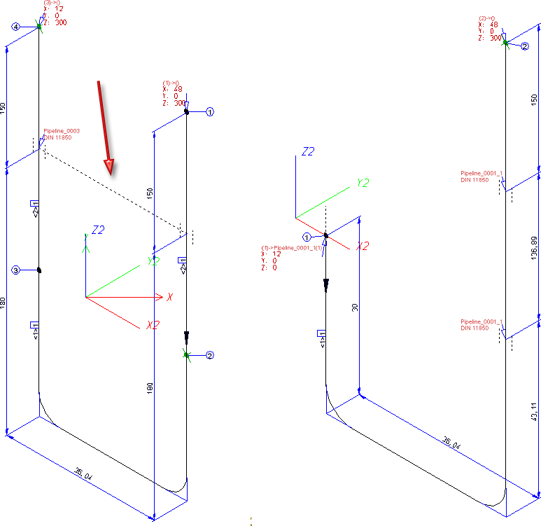
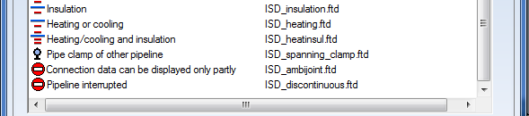
Instead of an item number tag, a configured tag will be created. It has been preset for this tag that it refers to the pipeline to which the clamp belongs. Furthermore, the content of the "Order note" attribute is involved here which containing, amongst other things, the standard and often also the concrete sub-type of the clamp. The contents of the tag can be specified on the Text objects tab of the isometry settings dialogue window. The corresponding entry is Pipe clamp of other pipeline.
Just like the item number tag, this text tag will only be placed at the lowest connecting point used.
Clamps of other pipelines are only drawn if the Indicate connected elements checkbox has been activated before isometry generation.
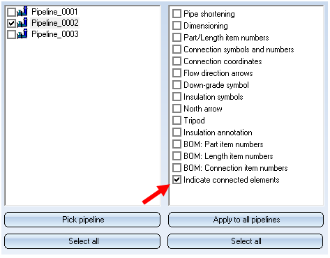
As this setting also affects other pipe parts and components, you can specify on the Symbols tab of the Isometry settings catalogue which elements will be indicated and which not.


Generate Isometry/Pipe Spool Drawing (PE/Iso) • Isometry and Pipe Spool Drawing (PE/Iso) • Isometry/Pipe Spool Drawing Functions for the Layout Plan