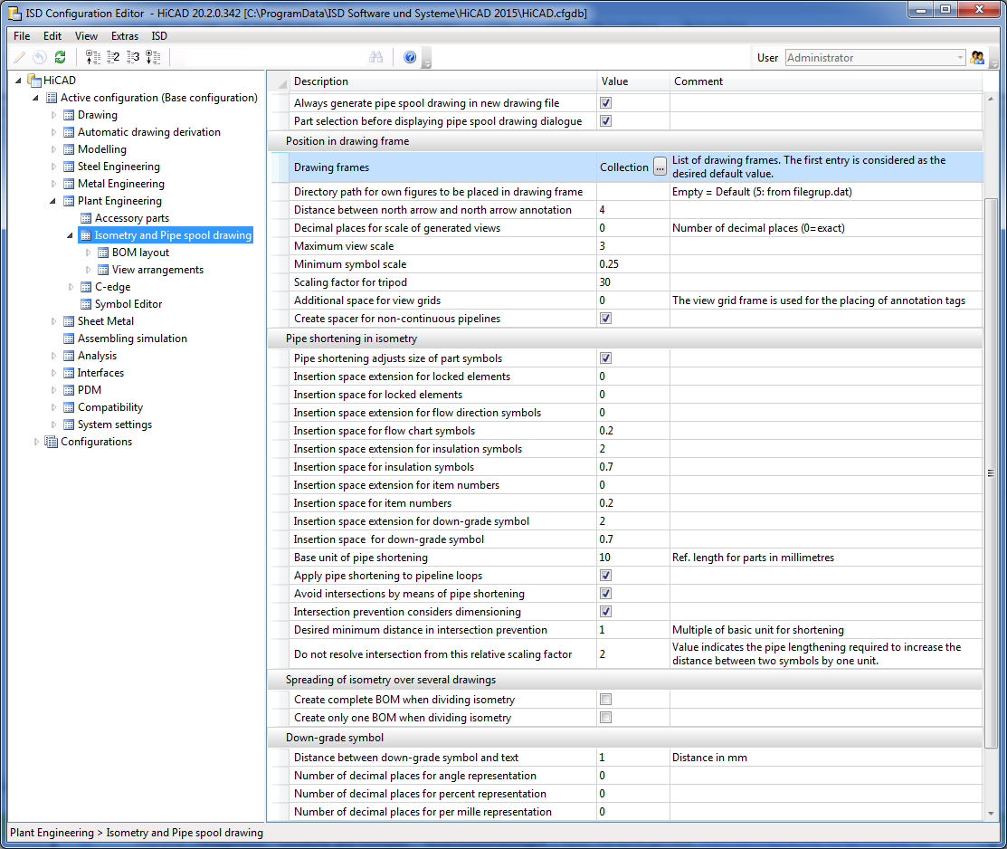
Settings in the Configuration Editor
In addition, you can specify various BOM layouts for isometries and pipe spool drawings at Plant Engineering > Isometry and Pipe spool drawing > BOM layout.
And at Plant Engineering > Isometry and Pipe spool drawing > View arrangements you can define view configurations for pipe spool drawings. These can then be selected in the Pipe spool drawing dialogue window.

Creation of new isometries and pipe spool drawings
These options influence the presettings in the Plant Engineering Isometry and Pipe spool drawing dialogue windows.
- Create document links
If this checkbox is active, the corresponding checkbox in the Plant Engineering Isometry and Pipe spool drawing dialogue window will also be active. The checkbox is deactivated by default. - Leave last isometry open
If you activate this checkbox, the last isometry in a series of generated isometries will remain open. - AutoClose isometric drawings
Via this checkbox you determine whether the Automatically save and close checkbox will be active when you call the functions AutoGenerate drawing (Iso) and Generate pipe spool drawing. The checkbox is deactivated by default. - Directory path for isometries and pipe spool drawings
Here you can preset the path for the automatic saving of the isometry/pipe spool drawings. Enter the desired file group (e.g. L:) from the Filegrup.dat file. The input field is empty by default, i.e. file group C: will be used. - Always generate pipe spool drawing in new drawing file
This checkbox determines whether the Create new drawing checkbox will be active in the Pipe spool drawing dialogue window when you generate a pipe spool drawing. The checkbox is deactivated by default. - Part selection before displaying pipe spool drawing dialogue
This setting determines whether a part or part chain needs to take place first or if the Pipe spool drawing dialogue window will be shown immediately when you call the Generate pipe spool drawing function.If you deactivate the checkbox, the query for the part or part chains will be suppressed. Instead, the Pipe spool drawing dialogue window will be displayed directly after function call, and all parts of the pipeline will be used for pipe spool drawing generation, The checkbox is active by default.
Position in drawing frame
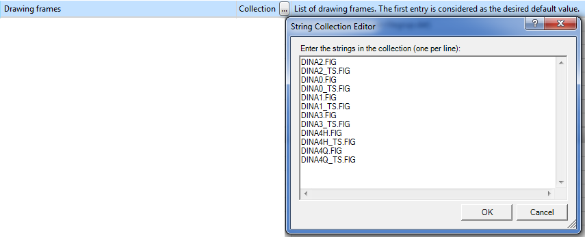
- Drawing frames
Here you speify which drawing frames are to be offered for selection in the isometry and pipe spool drawing settings. The list contains the file names of the 2-D parts for drawing frames . These 2-D parts are expected in the "Szenen" (=Drawings) directory. The drawing frame that comes first on the list will be preselected in the isometry and the pipe spool drawing dialogue. The rest of the sequence is insignificant.
When you call the functions for automatic isometry generation and pipe spool drawing generation, these settings will be checked. If adjustments are required, the dialogue window may therefore not appear immediately, but an appropriate message will be displayed.
Click here for further information.
- Distance between north arrow and north arrow annotation
Determines the distance of the text from the arrowhead. The default value is 4. - Decimal places for scale of generated views
The default value is 0. - Maximum view scale
Determines the scale that must not be exceeded when inserting drawings with only a few parts in the drawing frame. - Minimum symbol scale
If the view scale falls below the minimum scale when inserting large drawings in the drawing frame, the symbols will still be shown on the minimum scale. This prevents that the symbols will become too small. - Scaling factor for tripod
- Additional space for view grids
The view grid will be used for the placing of text tags. The default value is 0. - Create spacer for non-continuous pipelines
It can happen that pipelines are not continuous, but broken down in two or three parts. In such cases the isometry introduces spacers at the interruptions of the pipeline with a warning symbol attached to them. In this way, all interruptions in the pipeline will be visualized. If you do not want this, deactivate the checkbox. If the checkbox is deactivated, HiCAD will issue the warning message Parts not properly connected if there are small gaps between pipelines. This message will be suppressed if spacers are used.
Pipe shortening in isometry
- Pipe shortening adjusts size of part symbols
When inserting pipe parts in the layout plan the symbols will be scaled in such a way that the reach from connecting point to connecting point. If this checkbox is active, the isometry restores the original size of the symbols. This is the default setting. - Insertion space extension... / Insertion space...
A pipe shortening reserves space for each symbol that is to be drawn on/next to a pipeline. There are two parameters for every symbol - the "insertion space extension" and the Insertion space". The insertion space extension is a factor by which the representation of the pipe is to be lengthened if the symbol in question exists. The insertion length indicates how much of the space on the pipeline is to be reserved for the symbol. - Base unit of pipe shortening
Various setting options for pipe shortening refer to this base value. - Apply pipe shortening to pipeline loops
Up to HiCAD 2014 SP1, loops in the pipeline were disregarded for pipe shortenings. This behaviour has been changed as of HiCAD 2014 SP2, i.e. loops will now be considered. If you prefer the old behaviour, though, deactivate the checkbox. - Avoid intersections by means of pipe shortening
As of HiCAD 2015, part intersections will be automatically detected and resolved during isometry generation. If you do not want this, deactivate the checkbox. - Intersection prevention considers dimensioning
If this checkbox is active, HiCAD will minimise the number of intersections with and beneath the dimensioning lines. The checkbox is active by default. - Desired minimum distance in intersection prevention
This value determines from what distance elements of the isometry are no longer be interpreted as intersections to be resolved. This value is a multiple of the base unit of the pipe shortening. The greater the value, the greater the distance between the elements of the isometry after pipe shortening. - Do not resolve intersection from this relative scaling factor
To resolve an intersection, the intersecting elements must be moved away from one another. Since angles must not be changed in isometries, matching straight pipeline sections need to be found. In some cases, the angles in the isometry can be located so unfavourably that a straight section would have to be lengthened extremely in comparison to the created distance between the intersecting elements, which would lead to very unaesthetic isometric drawings. To avoid this, you can specify a maximum value here by which a straight section can be lengthened in order to increase the distance between intersecting elements by one unit. The default value 2 approximately corresponds to an angle of 60 degrees between the straight section and a virtual connecting line between the intersecting parts.
Down-grade symbol
These parameters influence the representation of down-grade symbols:
- Distance between don-grade symbol and text
- Number of decimal places for angle representation
- Number of decimal places for percent representation
- Number of decimal places for per mille representation
Spreading of isometry over several drawings
Here you can specify which BOM is to be created when an isometry is spread over several drawings:
- ...complete BOM
- ... only one BOM
Both checkboxes are deactivated by default.

Generate Isometry/Pipe Spool Drawing (PE/Iso) • Isometry and Pipe Spool Drawing (PE/Iso) • Isometry/Pipe Spool Drawing Functions for the Layout Plan