Reference Isometries and Manage via Database
Plant Engineering > Isometry / Pipe Spool Drawing > Auto-generate drawing 
Plant Engineering > Isometry / Pipe Spool Drawing > Generate pipe spool drawing 
Isometry + pipe spool drawing > Create > Auto-generate drawing 
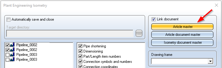
The drawing to which the isometric drawing belongs can contain the pipeline, from which it was generated, as a referenced part. In this case, you need to invoke the Link document option. Once generated, the item numbers of weld seams and parts are saved with the data of the original pipeline, and retained in the isometric drawing even if changed by re-creation of the isometric drawing.
Part master data and document master data for the pipeline are automatically created in the database. Attribute assignment can be preset, whereby you can specify diverse configurations and attribute assignments.

Attribute configuration settings
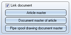
To specify attribute assignment, click the Document master, Article master or Isometry document master, or Pipe spool drawing document master button. The HELiOS document number will normally be generated according to a schema defined by the user. To do this, click the Isometry document master or the Pipe spool drawing document master button. Right-clicking an entry in the dialogue window and selecting Edit will open the Edit attribute templates dialogue.
To load a configuration, pick the corresponding name from the Configuration list box (configurations have been predefined by the ISD, e.g. ISO1 for isometries and SPOOL1 for pipe spool drawings). The corresponding attribute assignments will then be displayed.
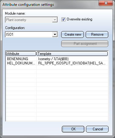
Use the Create new and and Remove buttons to create new configurations or remove existing ones. To edit a configuration, right-click an entry in the attributes list and select Edit in the context menu.
Change configurations
To change an existing configuration, select the required file from the Configuration list box. Right-click an entry in the Attribute list. A context menu containing the options Insert, Edit and Delete will be displayed.
|
Insert |
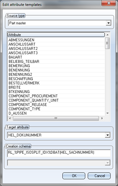
When you select this option HiCAD displays the Edit attribute templates dialogue box, thus enabling you add attributes to the current configuration. To insert an attribute, proceed as follows:
|
|
Delete |
To remove the current attribute entry from the configuration, right-click on the corresponding entry and choose Delete. |
|
Edit |
Enables you to edit the current attribute entry. As with the Insert function, the Edit attribute templates dialogue window will be displayed. For HELiOS attributes, language-dependent labels are available. When these attributes are selected via a listbox, the current attribute for each label will be shown as a tooltip. This is the case if you right-click an entry, select Insert or Edit, which opens the Edit attribute templates dialogue window. |
Create new configurations
To create a new configuration, click the Create new button. Enter the name of the new configuration and specify the attributes for this new configuration. The configurations will be saved to the WORKSHOPDAT.XML file in the HiCAD SYS directory. Making backups of these files on a regular basis is recommended!
Remove configurations
To remove a configuration, click the Remove button. The configuration will then be removed from the WORKSHOPDAT.XML file without any further queries.
 Please read the information given in the Classify pipeline articles section carefully.

Classify pipeline articles
If you select the creation of an article master when generating isometrics or piping plans, the article master in HELiOS is assigned the new classification Piping as of HiCAD 2020 SP2. However, this only applies to articles that you generate as of HiCAD 2020 SP2.
For the classification Pipeline, a corresponding input mask and the new HELiOS attribute PIPE_CLASS_NAME for the pipe class name are available in HELiOS.

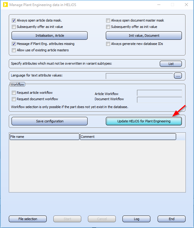
To use the new mask and the new attribute you must first update HELiOS using the tool DbplantDataImport.exe and then restart HiCAD.
Automatic transfer of the pipeline attributes
The attributes of a pipeline can also be automatically transferred from HiCAD to HELiOS when saving. To do this, proceed as follows:
- On the HELiOS PDM Ribbon tab at Others > Link
 > ..., select the function Article master sync when saving
 . Specify the assignments shown there.
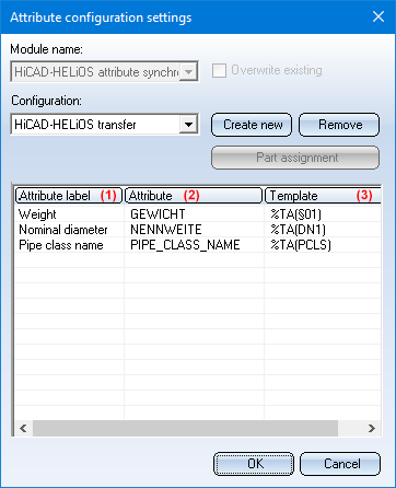
(1) Attribute, (2) Target attribute, (3) Creation scheme
End the function with OK.
- Since the assignments only become effective after a restart, close HiCAD.
- In the Configuration Editor at System settings > HELiOS, activate the Transfer part attributes to HELiOS checkbox.
- The next time you start HiCAD, the settings you made previously will apply.
Please note:
If you want to subsequently assign the classification Pipeline to existing articles, you must change this manually. To do this, click on the Classification  symbol in the dialogue window for the respective article and then activate the Pipeline checkbox at Plant engineering in the Classification dialogue window. You can then assign/change the attributes Nominal diameter, Weight and Pipe class name.
Further notes
Notes on isometries
In previous versions a Part geometry-Drawing link was created between the part geometry document of the pipeline and the layout plan, and a Part-Drawing link was created between the article master and the generated isometry documents. In particular constellations, this could lead to conflicts with Workflow functions. As of Version 2012, isometries in HiCAD will therefore use their own, isometry-specific links - by default, without release relevance and always linking to the part master.
In the example shown above, the pipeline part contains links to various documents:
- Bauteil-Teilegeometrie (Part - Part geometry) to the part geometry document (.KRA),
- Pipeline-Layoutplan to the layout plan and
- Pipeline-Isometry to a generated isometry document
Old documents with the formerly used link variants can be read, but may cause problems during processing (especially with isometry regeneration); we therefore recommend deleting the old isometry documents (e.g. by selecting Reset isometry). If the new link types have not been defined in HELiOS yet, an error message will be displayed when you try to start the isometry. The new link types will be automatically created after an upgrade of a new installation of HiCAD and HELiOS. Should this fail, the links need to be created manually.
Notes on pipe spool drawings
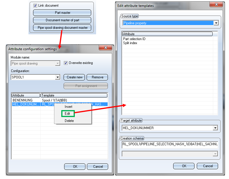
If you work with HELiOS, the HELiOS document number will normally be generated according to a schema defined by the user. This definition takes place via the Pipe spool drawing document master button in the pipe spool drawing dialogue. When you right-click the assignments that are defined here to edit them, the Edit attribute templates dialogue will be displayed.
In this dialogue you will find the Source type "Pipeline property", which in turn provides the "Part selection ID" attribute. Double-clicking this attribute adds the key %PIPELINE_SELECTION_HASH in the Creation schema field. This key will be resolved into the above-mentioned number that represents the selected parts.
As this key is part of the generated HELiOS document number, pipe spool drawings from different sections of the same pipeline will be represented by different document numbers. When the number is generated, supplementary parts such as clamps or seals will be ignored. Important: If parts are added to or removed from the pipeline, different numbers will be generated.
The new document link "Pipeline-Spool" now assigns the layout plan to a pipe spool drawing document. You can use the Linked documents function to view the corresponding links.

Generate Isometry / Pipe Spool Drawing (PE/Iso) • Isometry and Pipe Spool Drawing (PE) • Isometry and Pipe Spool Drawing Functions for the Layout Plan (PE/Iso)