New Bolting/Riveting
3-D Standard > Standard Parts > New bolting/riveting 
An expert system for mechanics is available for fitting complete boltings or rivetings. This system supports you during solving of standard problems, such as the design of a bolting or riveting. You can use a catalogue system to select rivets,bolts, washers, nuts, bores, countersinks and threads, thus constructing your individual bolting. Corresponding plausibility checks prevent inadmissible specifications. Only matching bolting or riveting elements according to DIN will be suggested, i.e. unsuitable elements will be excluded right from the start.
In addition, you can define the arrangement of the bolting or riveting - as an individual bolt/rivet or on a pitch circle. You can specify the values for the minimum projecting length and the minimum screw-in length individually.The advantages of this expert system become particularly apparent when you apply changes to already inserted boltings or rivetings. For example, you can open the data input dialogue directly by selecting the desired bolting or riveting. You can then choose, for instance, another thread runout.
When you call the New bolting/riveting function, the Bolted/riveted connection dialogue window will be displayed. Here, you can choose various elements for your bolting or riveting and specify further options. On the tabs of the dialogue window, you
can
- specify the components of the bolting or riveting,
- define further options, such as the projecting length, or load/create new bolting/riveting configurations, and
- create and process templates for boltings and rivetings.
The dialogue for the insertion of boltings or rivetings appears as soon as you click OK to end one of the tabs.
 Important:
- Do not forget to create backups your configurations regularly!
- By default, all components of a bolting or riveting set (bolts, rivets, washers, nuts) are BOM-relevant. If you do not want this, you can use the Catalogue Editor to to define the BOM-relevance of individual components of a set yourself.

'Parts' tab
You use the Parts tab to access all available bolts, rivets, washers, nuts, bores, countersinks and threads of which the bolting or riveting can consist.
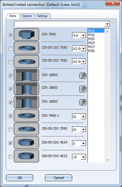
To select a part for the bolting or riveting, activate the relevant checkbox
![]() , and choose the desired sizes in the right-hand column.
, and choose the desired sizes in the right-hand column.
To select another element, e.g. another bolt, simply click the relevant graphic symbol. HiCAD then displays an overview of all available Standard Parts and Standard Processings. Choose the bolt you want and click OK to exit the selection window.
- If you have chosen a configuration file on the Options tab and have activated the List all saved configurations checkbox, HiCAD will check upon selection of a bolt whether the file contains any configurations for this bolt or rivet. If this is the case, you can select the desired configuration from the list box at the top of the dialogue window. If no configuration exists for the selected bolt or rivet, a corresponding message will be displayed.
- If you have chosen a configuration file on the Options tab and have deactivated the List all saved configurations checkbox, all configurations will be offered in the listbox, and not only the ones for the currently selected bolt.
![]() Please note:
Please note:
- If the composition of the bolting is a non-standard composition, this will be indicated by a message at the bottom of the dialogue window.
- Boltings do not need to contain bores, i.e. you can also insert boltings into existing bores.
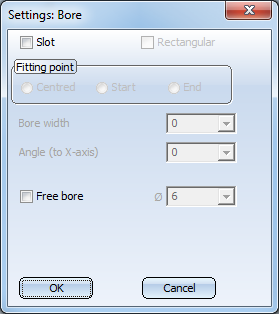
- Instead of bores and countersinks according to DIN, you can also use slots or free bores in boltings. To do this, click the
 icon and then enter the required data.
'Options' tab
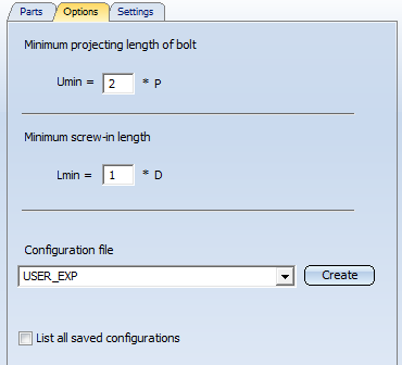
Minimum projecting length of bolt / Minimum screw-in length
HiCAD normally determines the minimum bolt projection length and the minimum bolt depth automatically. However, the Options tab allows you to change the default setting used.
- Lmin is the product of the bolt diameter D and any factor.
- Umin is the product of the pitch P and any factor.
Enter the factors to determine Lmin and Umin.
Configuration file
The composition of a bolting, i.e. the selection of its individual elements, can be saved in configuration files, which enables a later re-use. Via the Configuration File list box you can select the file the configuration of which you want to use, or to which you want to add further configurations.
To create a new configuration file, enter the name of the new file in the Configuration File input field, and click Create.
To load a configuration file, simply select its name from the list box.
The editing of a configuration file, i.e. the creation and modifying of configurations, takes place on the Settings tab.
If you activate the List all saved configurations checkbox, all existing configurations will be offered, i.e. not only the one for the currently selected bolt.
 The configuration files are saved to the HiCAD directory Kataloge\sys\configs.
'Settings' tab
You can use this tab to configure frequently used bolted/riveted connections and save them to a file that you select from the list box on the Options tab.
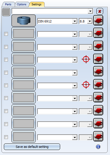
To define a bolted or riveted connection, proceed as follows:
- Select the bolt
type. To do this, click the bolt symbol, e.g.
 . Select the
bolt type and then the desired standard series.
. Select the
bolt type and then the desired standard series. - Click OK to exit the selection window. The bolt symbol in the Bolting window is automatically updated.
- Select the connection
elements. To do this, click the corresponding symbol, e.g.
 or rectangle
  . Select the desired type and
then the standard series.
. Select the desired type and
then the standard series. - Click OK to exit the selection window. The selected connection element is displayed as a symbol and the corresponding checkbox automatically updated.
- Before saving the configuration, specify whether you want the settings to be saved as basic settings. If so, click the Save as default setting button. When loading this bolt/rivet type via the Parts tab, the connecting elements assigned to this type will be displayed and activated. The default setting saved in the configuration file will be indicated by a corresponding text.
- To save the configuration, enter its name in the input field at the top of the window and click the Save
 icon. The configurations will be saved to the file that you have selected on the Options tab.
If not all available types are displayed during selection of bolts or
connection elements, you can use the Add new ... ![]() function in the corresponding row. This function enables
you to enhance the selection lists for bolts and connection elements. In this way you can add, for example, fasteners from the Factory standards > User-defined fasteners catalogue, such as anchors or dowels.
function in the corresponding row. This function enables
you to enhance the selection lists for bolts and connection elements. In this way you can add, for example, fasteners from the Factory standards > User-defined fasteners catalogue, such as anchors or dowels.
Use the  button to delete the configuration from the file you selected on the Options tab.
Bolting configuration: Example

Insert Boltings/Rivetings (3-D) • Boltings (3-D) • Change Boltings/Rivetings (3-D)