Change Boltings/Rivetings
3-D Standard > Standard Parts > Bolting  > Change
Use the following functions to apply subsequent changes to already inserted Standard Parts, boltings and rivetings:
|
|
||
|
|
Changes the insertion point / grid for the bolting. |
|
|
|
Changes the representation of the bolting. |
|
|
|
Adjusts the bolting after applying modifications to the bolted geometry. |
|

|
Settings | Enables you to specify the settings for boltings. |
 Alternatively, you can also access the Change functions via the context menu for boltings (right-click bolting). Here you can find the following additional functions:
|
|
Break up bores Removes the link between bore and bolting. In case of any subsequent changes to the bolting, you will then need to adjust the holes manually. |

|
Bolt length Changes the length of a bolt. |


Process boltings
3-D Standard > Standard Parts > Bolting > Process 
You use this function to replace fitted standard parts, components of a bolting or standard processing by relevant objects of another type or another size.
- Identify an edge of the standard part or the standard processing.
- HiCAD displays a corresponding dialogue window for standard parts, standard processes or boltings. Select the replacement object or the new size.
- Click OK to exit the dialogue window.
Position/Grid
3-D Standard > Standard Parts > Bolting > Position/Grid 
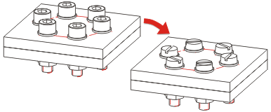
You use this function to change the fitting position of standard parts, standard processings and boltings as well as the arrangement of standard part images that have been fitted on a grid.
- Identify an edge of the standard part or the bolting.
- The Grid menu opens. Choose the grid you want and, if required, enter the number of objects as well as the necessary distances/angles. Operation is similar to a new fitting.
- If you want to change the fitting position, the fitting direction or the reference point, use the right mouse button to activate the context menu before fitting. If desired, you can also reverse the direction of the bolting.
- Make the changes you want by selecting the relevant function.
- Specify the fitting position.
 Please note that you can only invert boltings with identical bores at their start and end.
Representation
3-D Standard > Standard Parts > Bolting > Representation 
Simplify > Change > Change representation
This function enables you to make subsequent changes to the representation of existing standard parts, standard processings and boltings.
- Geometry
You can show/hide holes, standard parts, axes and threads here by activating/deactivating the checkboxes.
- Detailing
If Exact is chosen, the bolt heads are represented in detail. Especially for large drawings containing very many boltings it often makes sense to use the Compressed (2) representation to increase the performance of the program. If you want boltings in compressed representation to be considered for identical part search, BOM creation, or product structure transfer to HELiOS, select the Ref. BOM (3) representation.
- Production
This setting is only relevant for steel engineering. First choose Show axes and then the type of production.
 - Options
By activating the relevant radio button, you can define whether you want the change to apply to individual boltings, to all boltings of an active part, or to all boltings of the drawing.
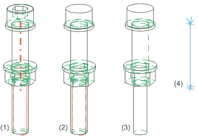
(1) Detailed representation on, (2) Detailed representation off, with thread without axis, (3) Detailed representation off, without thread and axis, (4) Only axis
Update bolting
3-D Standard > Standard Parts > Bolting > Update 
Use this function to update boltings,e.g. adjust them to the changed thickness of bolted plates. You can apply the function to
- individual boltings,
- all boltings of the active part, or
- all boltings of the entire drawing.

Boltings and Rivetings (3-D) • Standard Parts, Boltings, Rivetings, Weld Seams (3-D)