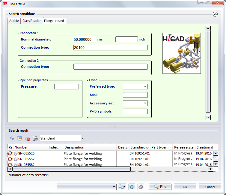
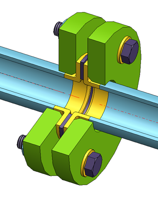
When you insert flanges, please note that Connection 1 always refers to the flange connection side while Connection 2 refers to the pipe connection side.
Project: HiCAD Plant Engineering
|
When you insert flanges, please note that Connection 1 always refers to the flange connection side while Connection 2 refers to the pipe connection side. |
|
When working with user-defined variants for flanges or parts with flanges, please read the Notes on bolted flange connections in the Creating New Parts and Variants topic!

Plant Engineering > New > Pipe parts > Flange 
When you insert a flange, you have the following insertion options.
|
|
|
|
|
|
|
|
Connect flange
When you select the Connect option, (additional) search criteria from the properties of the target part and its selected connection are used (Attributes: NENNWEITE (nominal diameter) and ANSCHLUSSART (connection type). Let us assume that the standard designation of an accessory is contained in the ANSCHLUSSART attribute and it this accessory is a flange, it is added to the search criteria in the NORMBEZEICHNUNG (standard designation) attribute. The insertion direction of the flange depends on the type of target connection, i.e.
If the target object is a flange, and the target connection is on the flange surface, HiCAD inserts an identical flange. HiCAD now displays the crosshairs, thus enabling you to select a new target point for the fitting of the next flange. Search criteria is enhanced by data extracted from the NORMBEZEICHNUNG of the previously inserted flange.
|
|
|
Connect 2 flanges
Select a part with the crosshairs. HiCAD inserts suitable flanges in the appropriate direction in all connections on the part, provided that the connection is located on a guideline and has not yet been joined to the connection of another part. In this case, the same search criteria as those for individual flange insertion apply. |
|
|
Connect all
HiCAD inserts suitable flanges in the vacant flange connections on all guidelines of the active pipeline, provided that the respective connections are located within a guideline, and are not orientated outwards at the end of a guideline, If a guideline end point is located on a flange connection of a part that does not belong to the active pipeline, HiCAD inserts a suitable flange anyway. In this case, the same search criteria as those for individual flange insertion apply. |
|
|
On guideline ends
|
 When connecting one or several flanges, the search criteria for the flange to be fitted always refer to the flange connection to which the flange is to be attached. This means that the nominal diameter assigned to the pipeline or the guideline is always ignored, i.e. even if the Ignore nominal diameter option has not been activated. If the flange connection to which the part is to be fitted belongs to a flange, the same flange is inserted as a counter-flange; this applies even if a pipe class not containing this flange has been assigned to the pipeline.
Plant Engineering > New > Pipe parts > Blank flange 
This function is only available when guideline mode is active, and can be handled almost in the same way as the Connect flange function. Provided that the attribute exists for the target object, DRUCK (pressure) attribute settings are added to search criteria.
A blank flange can also be attached to a flange which is located on the end of a guideline. In this case the blank flange will not be placed on a guideline. The search criteria for the blank flange to be fitted always refer to the flange connection to which the flange is to be attached. This means that the nominal diameter assigned to the pipeline or the guideline is always ignored, i.e. even if the Ignore nominal diameter option has not been activated.
The following parts are available as "loose flanges" in HiCAD:
Loose flanges can not only be placed through an automatism during automatic placing of parts on guidelines, but also be added to a pipeline manually.
Please note the following:
Please note:
HiCAD supports the insertion of welding necks with loose flanges. In the standard part inventory for plant engineering, appropriate variants exist for this purpose.
In the form of the variants KM10357_WN_DIN.VAA and ROFI10357_WN_ISO.VAA, the standard part inventory contains two part families, which are classified as "real" flanges, but are in fact only welding necks.
In total, the following welding neck variants are available:
|
Variant |
Standard designation |
|
|---|---|---|
|
KM10357_WN_DIN.VAA |
Kieselmann 10357 |
|
|
ROFI10357_WN_ISO.VAA |
RO-FI 10357 |
Contains all sub-types of the modelled welding neck. |
|
ROFI10357_WN_ISO_R1.VAA |
RO-FI 10357 R1 |
Contain each one portion of the sub-types from ROFI10357_WN_ISO.VAA. |
|
ROFI10357_WN_ISO_R2.VAA |
RO-FI 10357 R2 |
|
The variants refer with their connection type to the (also new) loose flanges of the DIN 2642 standard, which are classified as fasteners:
|
Series |
Variant |
Standard designation |
|---|---|---|
|
1 |
N2642_LF_R1.VAA |
N2642 R1 |
|
2 |
N2642_LF_R2.VAA |
N2642 R2 |
The loose flanges of the series 1 match the variant ROFI10357_WN_ISO_R1.VAA. The loose flanges of the series 2 match the variants ROFI10357_WN_ISO_R2.VAA and KM10357_WN_DIN.VAA.
To model your own welding necks, you can choose between the following two options:

Pipe Parts (PE) • Part Selection - Catalogue or Database (PE)
|
© Copyright 1994-2019, ISD Software und Systeme GmbH |


