 Please note:
Project: HiCAD Plant Engineering
Isometry + Pipe spool drawing > Settings
Isometries containing representations of entire pipelines or pipeline details can now be divided into two or more partial isometries. For each of these partial isometries an own drawing sheet will be created.
Please note:

Isometry + Pipe spool drawing > Settings > Specify division 
Use the Specify division function to break up an isometry drawing that shows a complete pipeline or only part of it into two or more partial isometries.
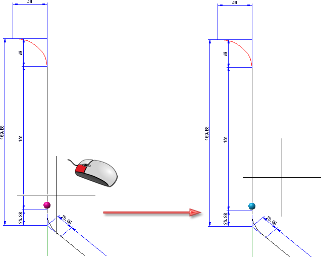
When you move the cursor over the isometry, possible division points will be marked in a different colour (Marking colour 1). Left-click to accept a marked point as a division point. When you move the cursor away from the division point, its colour will change (Marking colour 3).
If the isometry has already been subdivided into several drawings, the corresponding division points will be highlighted (Marking colour 3) as soon as the cursor is close enough to the pipeline to be processed.
If an already selected division point is selected again, the related division will be removed.
Right-click or press ESC to cancel the function without applying the selected division points.
Press the middle mouse button to apply the selected division points and end the function.
When re-generating the isometry with the function Isometry+Pipe Spool Drawing > Create > New, it will be divided according to the specified division points. The original isometric drawing will be retained.

(1) Original isometry with division point, (2) and (3) Divided isometries with alternating auto-generated references
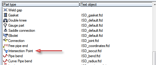
A special text object type exists for division point annotations (e.g. the division points in the isometry), which can be configured in the isometry settings like other text object types. Reference numbers can thus be generated automatically.
If you want to re-generate a pipeline isometry spread over two or several sheets, the spreading will be shown in a dialogue box when you call the function again (out of the layout plan). You can now select either the entire pipeline isometries, but also individual sheets for the re-generation.

![]() Please note:
Please note:
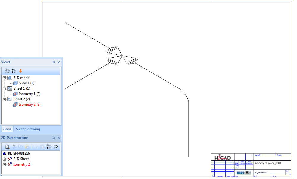
Example:
Take a look at the layout plan and its corresponding isometry shown below:
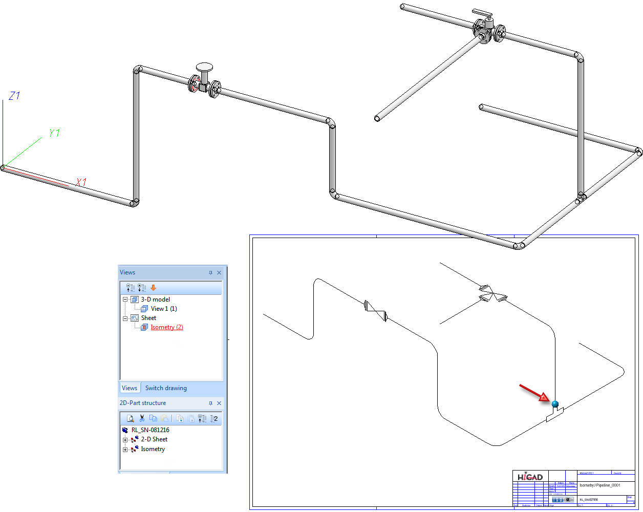
If you divide the isometry at the blue point (see red arrow) and then generate it again, the sheet with the current isometry will be deleted, and two new sheets for the partial isometries will be generated.


Isometry + Pipe spool drawing > Settings > Undo division 
Plant Engineering > Isometry / Pipe Spool Drawing > Settings > Undo division
Load the isometric drawing in which you have specified one or several division points. To undo the division and spreading over several sheets, proceed as follows: If you have already specified the division points in the layout plan, load it.
Now call the Undo division function.
When you now re-generate the isometry, the division and spreading of the drawing over several sheets will be undone.
If the pipeline from which the isometry was generated is contained in the isometry as a referenced part (see Reference Isometries and Manage via Database), it is possible that the pipeline will be processed further after division of the isometry: Further parts might be added, or existing parts might be replaced with other parts. These parts are initially not assigned to any of the split isometries.
Before re-generating the isometry from the layout plan, HiCAD therefore checks whether there are any parts which are not assigned to any split isometry yet.
Possible are two cases:
In this case the user will be asked whether HiCAD should execute the automatic assignment.
In this case HiCAD asks if you want to fully reset the isometry division.
In both cases the previously unassigned parts will be highlighted in the layout plan.
Example of Case 1
The division (Isometry 1 and 2) takes place at the connecting point in the red circle. The right pipe (3) was added after the isometry division.
After confirming with Yes:
Example of Case 2
The division (Isometry 1 and 2) takes place at the connecting point in the red circle. The middle pipe was removed and replaced with an new pipe (3).

After confirming:

Generate Isometry/Pipe Spool Drawing (PE/Iso) • Isometry and Pipe Spool Drawing (PE/Iso) • Isometry and Pipe Spool Drawing Functions for the Layout Plan
|
© Copyright 1994-2019, ISD Software und Systeme GmbH |