Steel Engineering - What's New

Service Pack 2024 SP2 (V 2902)
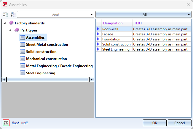
Civil Engineering - Part type catalogues
Due to many customer requests, the Part type catalogue, 3-D function is once again available in the Civil Engineering functions docking window under Civil Engineering, General > Civil Engineering - Part type catalogue.
Insert new beam - modified and extended dialogue
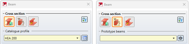
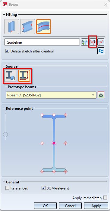
The dialogue window of the Insert new beam  function has been slightly changed and extended.
- The Source are has been renamed to Cross-section and has been moved been moved to the top of the dialogue window, above the Fitting area.
- The option Adopt cross-section from reference profile has been moved to the Cross-section area and the symbol for Open/close configuration window for prototype beams has been changed for prototype beams.
-
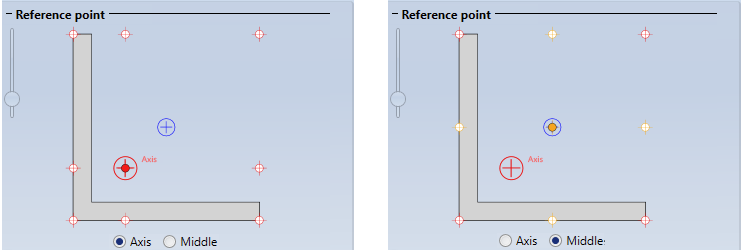
Previously, only the Centroid of the beam cross-section and the corresponding beam axis points could be selected as the reference point.
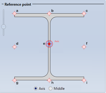
As of SP2, the Middle (=surface cross-section) of the bounding box, i.e. the smallest cuboid that completely encloses the beam, can also be used instead of the centroid. However, this only has an effect on asymmetrical beams and profiles, for example L-beams.
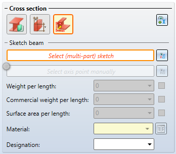
- The functions Beam from sketch and Multi-part beam from sketch have been integrated into the dialogue.
The previous functions
 Beam from sketch,
 Beam from sketch, as sub-part, and
 Multi-part beam from sketch
have therefore been removed from the Steel Engineering Ribbon and moved to the Steel Engineering > New > Beam  > ... pull-down menu, under Up to HiCAD 2022.
Copying connections on API basis
Previously, only connections based on a design variant could be copied using the Copy connection/design variant  function. As of HiCAD 2024 SP2, this is also possible for connections that are realised as API variants. This affects the following connections:
Railing Configurator
Post made of round steels
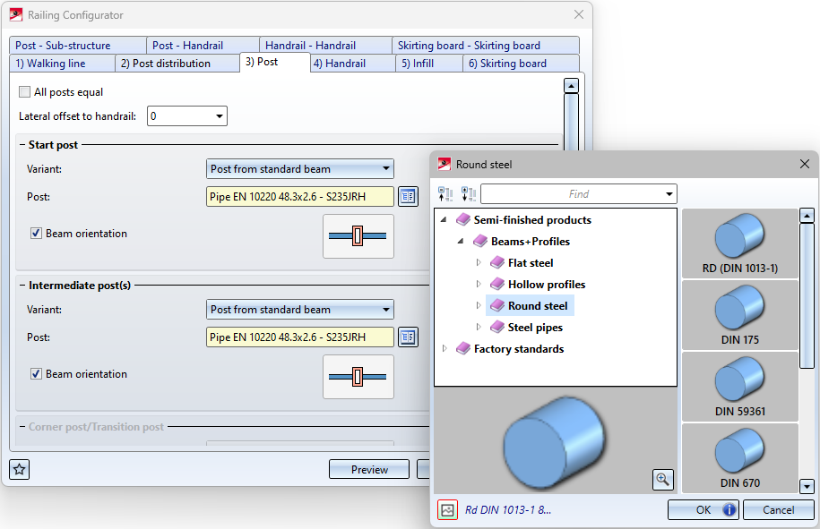
As of HiCAD 2024 SP2, profiles from the catalogue Semi-finished products > Beams+Profiles > Round steel can also be used as posts.
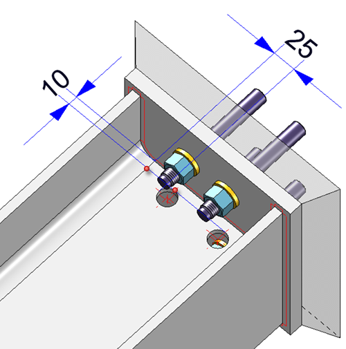
Straight cut on handrail
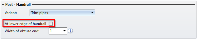
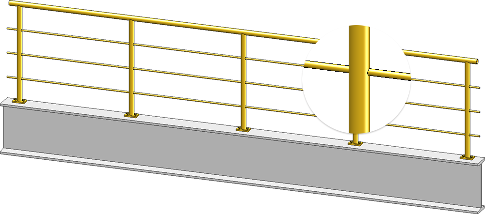
On the Post - Handrail tab, the At lower edge of handrail checkbox is also available for the Trim pipes variant. If the post is to be cut straight at the lower edge of the handrail, activate this checkbox.
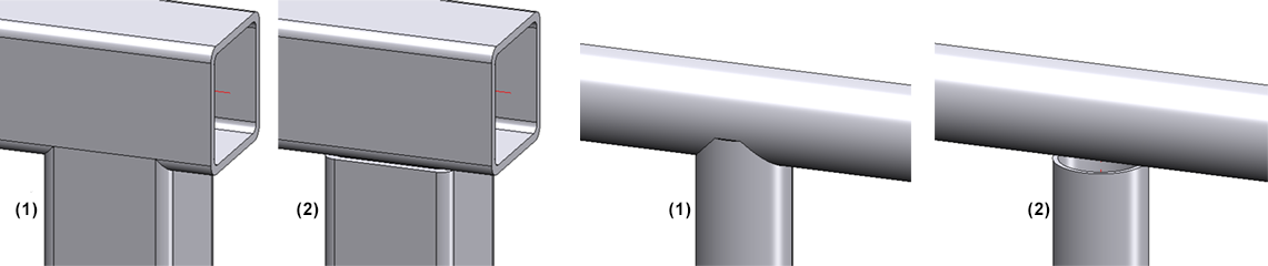
(1) Trim pipe, (2) Trim pipe, at lower edge of handrail
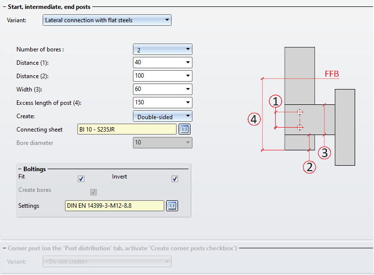
Post - Sub-structure: Lateral connection with flat steels
On the Post - Sub-structure tab, there is another connection variant called Lateral connection with flat steels available. Here, the posts are attached to the side of the beam using connecting plates (sheet metal parts or flat steels)
Post - Handrail - Console (round bar)
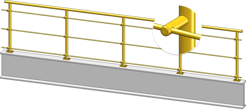
A further variant called Console (round bar) is available for connecting the handrail to the post. Here, the handrail is positioned in front of the wall console connection (own production).
Continuous infills
As of SP2, infills can be configured for an entire segment independently of the posts. There is then one infill per segment. The components of the infill are summarised in an assembly called Continuous infill.
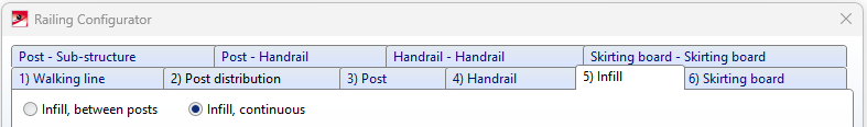
Two variants are available for continuous infills:
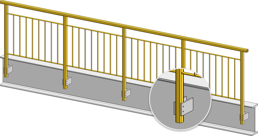
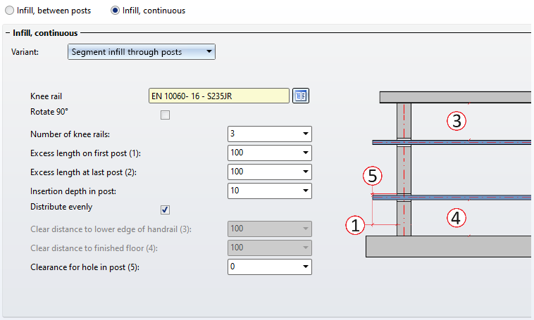
Segment infill through posts
Here, the knee rails run through the posts. The knee rails can be evenly distributed or have a certain distance to the handrail and finished floor.
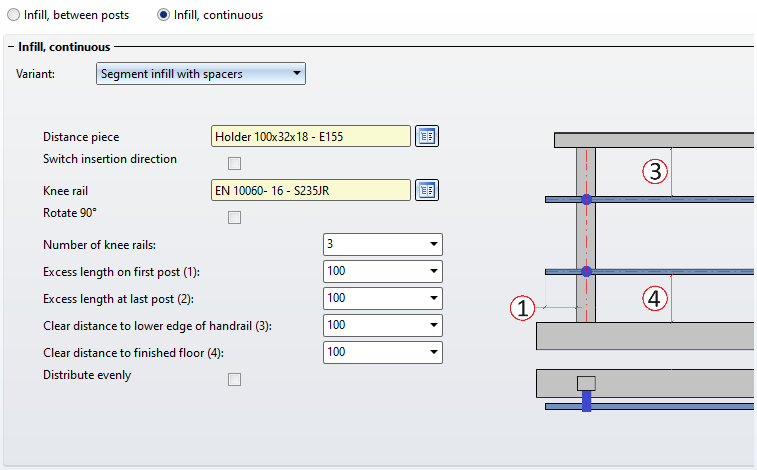
Segment infill with spacers
In this variant, spacers are placed on the posts. The knee rails then pass through the spacers. They can be evenly distributed or have a certain distance to the handrail and finished floor.
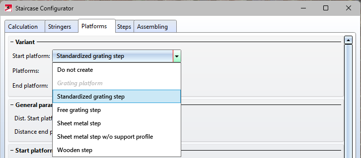
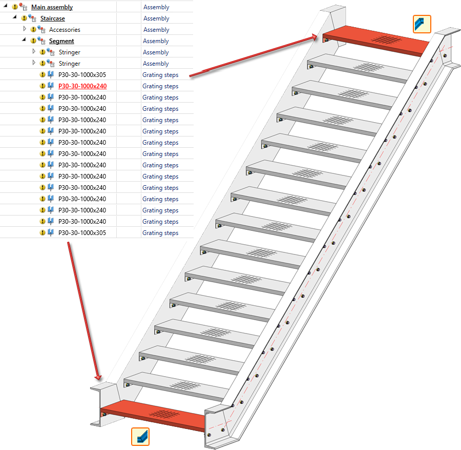
Staircase Configurator - Start/end platform as a step
From SP2, a new type of stair start and stair end is available on the Calculation tab of the Staircase Configurator, which can be used to install steps at a stair start/end instead of platforms.
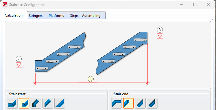
If these options are selected, step variants can be selected for the stair start/end instead of a platform on the Platforms tab.
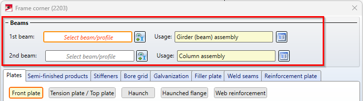
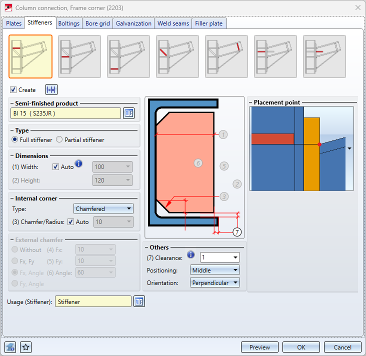
Redesigned Frame corner dialogue (2203)
The dialogue for the Frame corner (2203) connection has been redesigned in SP2.
- The selection of the two I-beams to be connected now takes place directly in the dialogue window. The selection can also be corrected in the dialogue window. Previously, the beams had to be selected before the dialogue window was displayed.
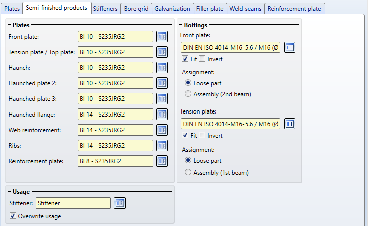
- The semi-finished products of the individual components of the frame corner can be selected centrally on the new Semi-finished products tab. This also applies to the bolting on the front plate and the tension plate. The previous Bolting tab is therefore no longer available from SP2.
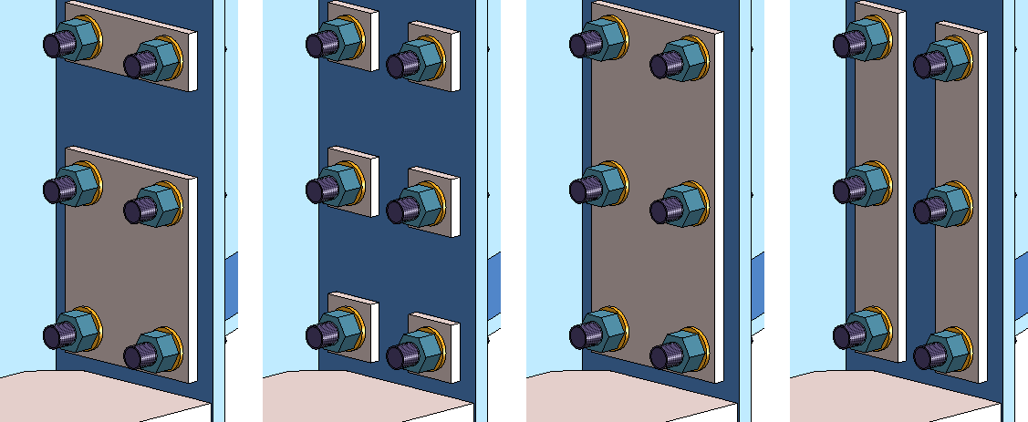
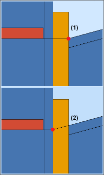
- As of SP2, a separate tab called Reinforcement plates is now available for this type of plates. The corner processing can be selected here if desired. The chamfers can either be chamfered (45°) or filleted. In addition, the reinforcement plates can be connected both horizontally or vertically. The vertical connection can also be made row by row.
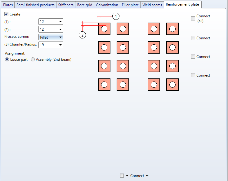
By activating the corresponding checkboxes, you can individually define which rows/columns are to be linked, e.g.
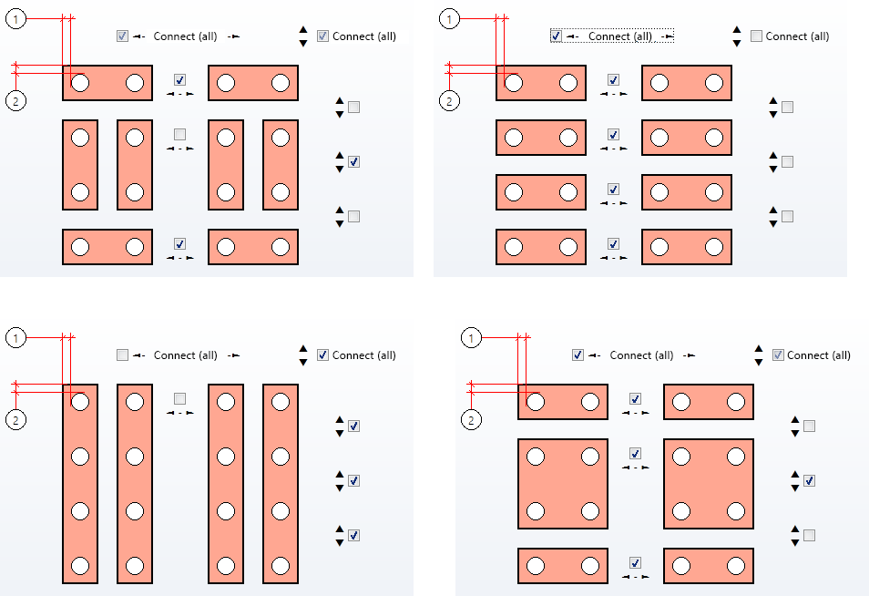
Some examples are shown below:
End plate (2102) - Base position
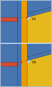
When connecting End plates (2102) to a beam, the position of the base can now be influenced. The Shorten beam checkbox has been added to the Base tab for this purpose. If the checkbox is active, the beam will be shortened by the height of the base when the plate is inserted.
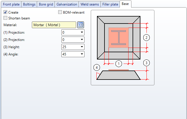
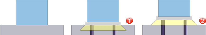
(1) Shortening of the beam by the plate thickness including filler plates, (2) Beam additionally shortened by base height
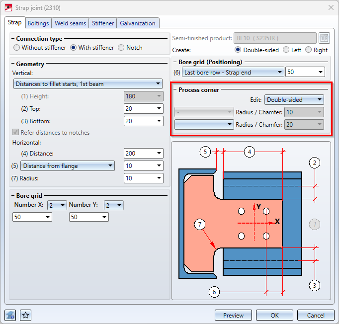
Strap joint (2310) - Chamfers of straps
With the Strap joint (2310) , it was previously only possible to fillet the corners of the strap. As of SP2, chamfering is also supported.
Service Pack 2024 SP1 (V 2901)
Development attributes for Steel Engineering plates
As with Sheet Metal parts, the attributes Rectangular surface area of development (§S2D) and Surface area from development contour (§SOC) are also now calculated for Steel Engineering plates if the settings in the Configuration Editor at Modelling > Part properties in the Sheet Metal area are set accordingly.
Railing Configurator
Faster start
The start of the Railing Configurator has been significantly accelerated with Service Pack 1.
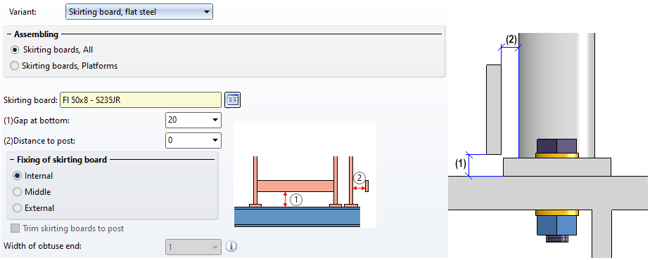
Distance between skirting board and post
The Skirting board tab has been expanded. The distance between the skirting board and the post can now be specified here.
Distance between handrail and cross-member
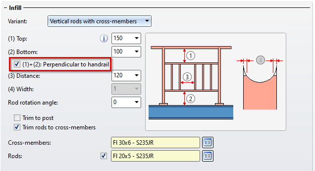
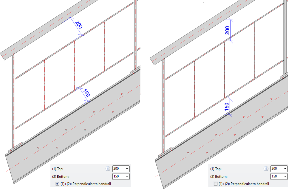
On the Infill tab, the additional checkbox Perpendicular to handrail is available for infills with cross-members and infills with bottom cross-members, e.g.
If the checkbox is activated, the distance at the top/bottom is interpreted as a vertical distance between the handrail and cross-member, or cross-member and beam. This only has an effect on sloping railings.
The following illustration shows the difference.
Feature for mitre cuts
For mitre cuts, a feature with the name Mitre cut is created for both processed beams. From SP1, the two features are linked. This means that if changes are made to one of the features, the other feature is automatically changed accordingly. If, for example, the mitre cut feature is deleted from one of the two beams, then - unlike previous HiCAD versions - the feature of the other beam is also deleted.
Linking the two features improves the use of the function for variable-controlled assemblies, e.g. for user-defined infills in the Railing Configurator. Previously, the feature recalculation, which is carried out in particular when variables are changed, could lead to undesirable results. The image below shows such a case:
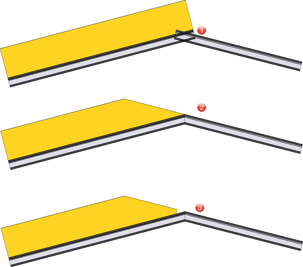
(1) shows the initial state, (2) the result as of HiCAD 2024 SP1, (3) an undesired result that could occur before HiCAD 2024 SP1.
This new behaviour does not apply if the mitre is created via the HiCAD API.
Civil Engineering - Part type catalogue, 3-D
The Civil Engineering - Part type catalogue > 3-D function in the Civil Engineering functions > Civil Engineering, general docking window contained functions that have since been replaced by new developments and are therefore no longer required. The function is therefore no longer available as of SP1.
Galvanization holes on beams
In the settings for the galvanisation holes on the beam, the Y-distance of the bores now refers to the fillet on the beam and not to the flange as before. This applies to the following connections:
- Front Plate Connection to Web/Flange (2320) ,
- Front Plate Connection to Web, Double-sided (2322),
- Front Plate Connection to Flange (2330),
- Column Connection, Frame Corner (2203) and
- Column Connection, Frame Corner (2204).
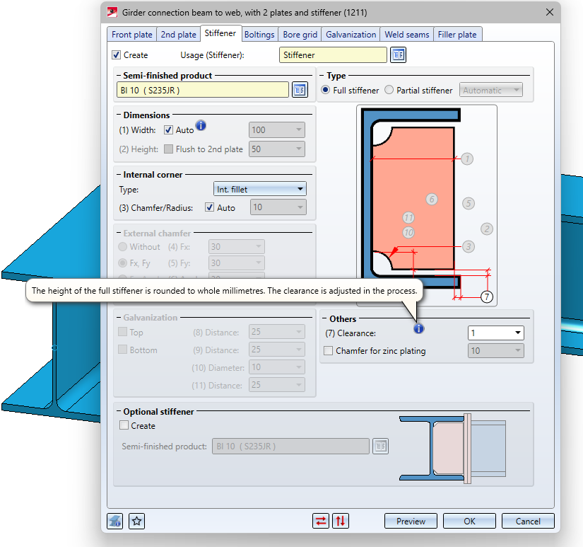
Clearance for stiffeners
When inserting stiffeners, the height of the full stiffener is rounded down to whole millimetres. The clearance is automatically adjusted.
This applies to the following design variants:
- Stiffener (2401)
- Purlin Joint - 1 Girder/1 Purlin (3206),
- Front Plate Connection to Flange (2330),
- Strap Joint (2310),
- Beam to Web with 2 Plates and Stiffener (1211),
- Column Connection, Frame Corner (2203) and
- Column Connection, Frame Corner (2204).
This is indicated by an info symbol in the dialogues for these variants.
Major Release 2024 (V 2900)
Insert new beam
The function Insert new beam has been extended:
- When inserting beams along a guideline, it is now also possible to process the sketch in the dialogue window.
- Two sources for inserting beams or profiles are distinguished :
Via catalogue...
With this option you insert beams from the allowed catalogues mentioned above at Semi-finished products or Factory standards.
Prototype beam...
With this option you can insert configurable prototype beams.
- Beam and profiles from the catalogues Factory standards > Series and Factory standards > Factory beams can now also be inserted.
Connections
New connection - Gusset plate (2510)
In the Civil Engineering functions docking window the new design variant Gusset plate (2510) is available at Steel Engineering > Connections > Web/flange to web/flange.
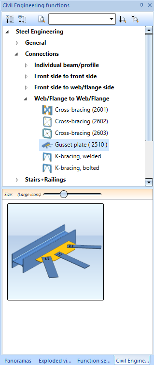
With this new design variant, any beam/profile can be connected with one to three beams/profiles by means of a gusset plate connection - as it often occurs in hall construction.
The beams/profiles to be connected must fulfil the following criteria:
- The beams/profiles must be of the type steel pipe, hollow profile, L-beam, round or flat steel.
- In the case of hollow sections, steel pipes and round steels, the X-axes of the beams/profiles must lie in one plane. This plane must intersect the connecting beam/profile at a planar facet and be parallel to the X-axis of the connecting beam/profile.
- Flat steels and L-beams must have at least one common plane in which the gusset plate can lie.
- If more than one beam/profile is connected, all beams/profiles to be connected must be of the same type. This means that the beams/profiles must be
- all flat steels or
- all L-beams or
- a mix of steel pipes, hollow profiles and round steels.
The connection of an L-beam and a steel pipe, for example, is not possible.
The connection consists of a gusset plate, the connection plates between gusset plate and the beam/profile to be connected and - optionally - the bolting between gusset plate and connection plate. Gusset plates are steel plates, the connecting plates can be of the flat steel or steel plate type.
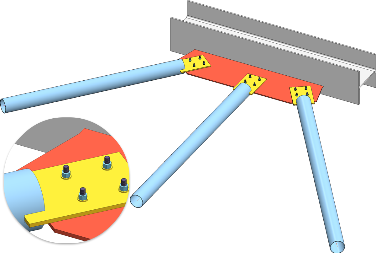
Gusset plate connection with three steel pipes
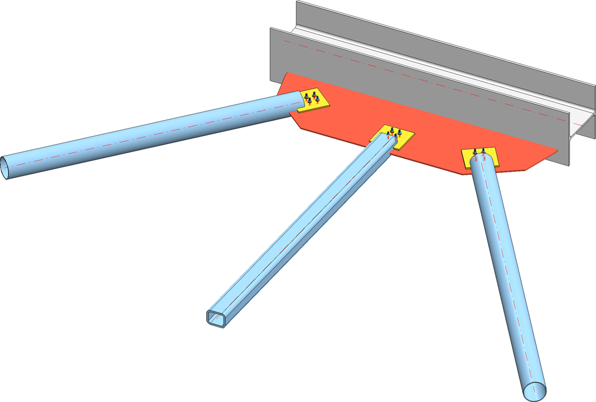
Gusset plate connection with two steel pipes and one hollow profile
If the beam/profile to be connected is of the flat steel or L-beam type, then no connecting plates will be created.
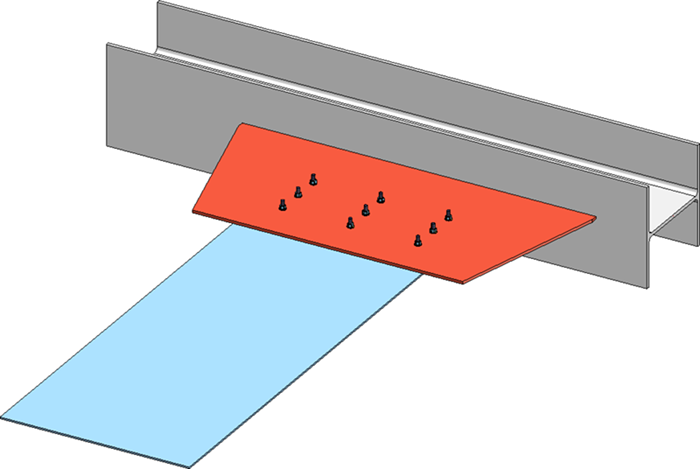
Connection of a flat steel profile
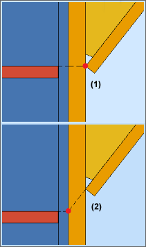
Frame corners - placement points for stiffeners
The Frame corner 2203 connection has been extended with placement points for the stiffeners on the 2nd beam. The stiffeners are installed relative to the selected placement point. Possible placement points are:
- Web of the connecting beam (1)
- Flange of the connecting beam (2).
The Stiffeners tab has been extended accordingly.
|
|
|
|
|
|
|
|


This extension also applies to Frame corner 2204.
Beam to web, with 2 plates + stiffener - Filler plates
The Design variant Girder connction beam to web, with 2 plates + stiffener (1211) now supports the installation of filler plates between the face plate and the 2nd plate, i.e. the plate on the beam to be connected. For this purpose, the dialogue window has been extended by the Filler plates tab.
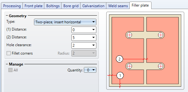
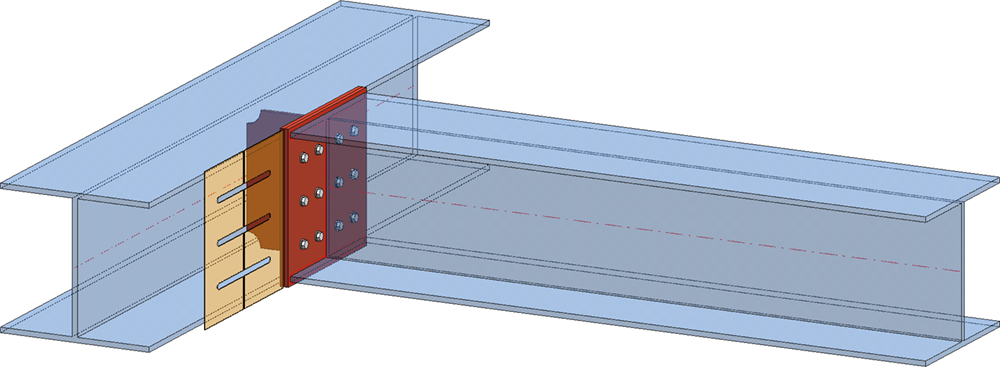
Girder connection, filler plate not pre-planned
Cross-bracing (2601) with turnbuckle and blade screws
With this Design variant, the cross-bracing can now also be installed with a turnbuckle according to DIN 1480 SP.
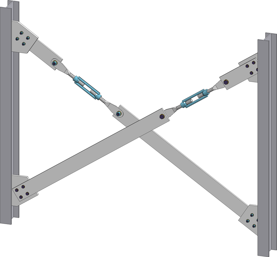
For this purpose, the Fixing tab has been extended accordingly.
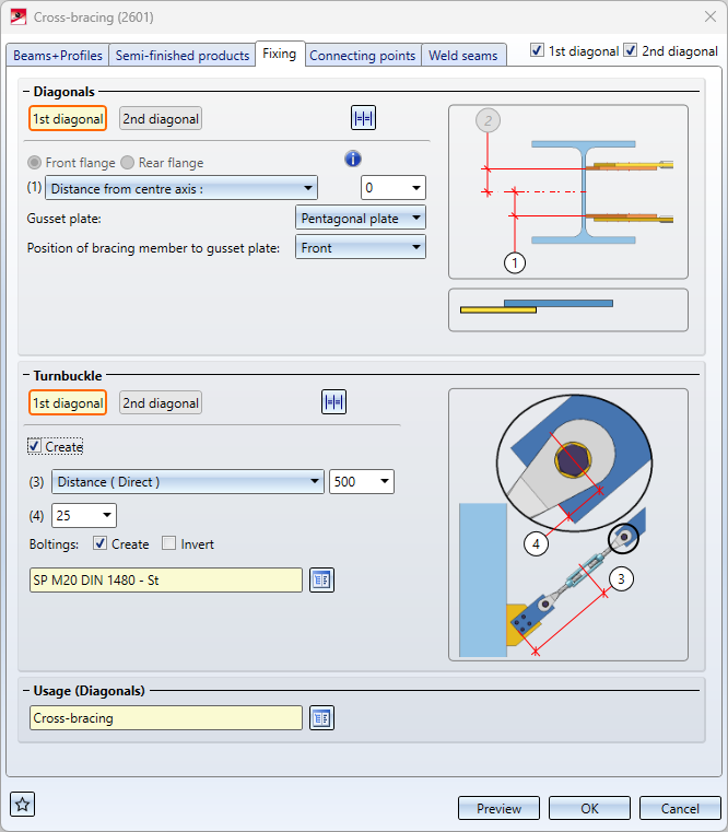
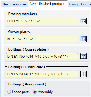
You define the mounting of the turnbuckle to the bracing members on the Semi-finished products tab.
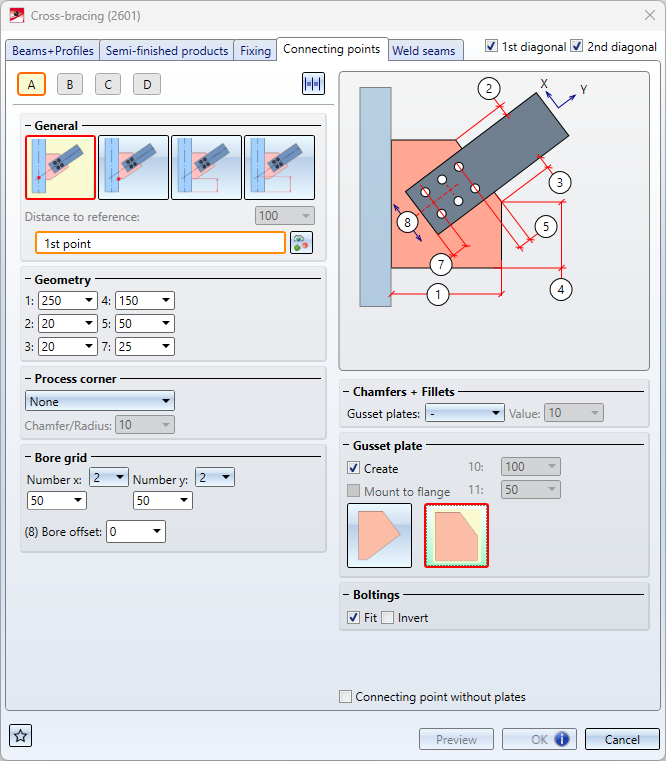
Cross-bracing without gusset plates and connecting plates
If for the connections Cross-bracing (2601) and Cross-bracing (2602) on the tab Connecting points for the connection point the option
Point (as intersection point of axes)
is selected for the connecting point on the tab Connecting points, the insertion at the corresponding end can now also be carried out without gusset plates and connecting plates. To do this, activate the checkbox Connecting point without plates. For example, you can subsequently generate a Gusset plate (2510) connection at these free ends or install a connection manually.
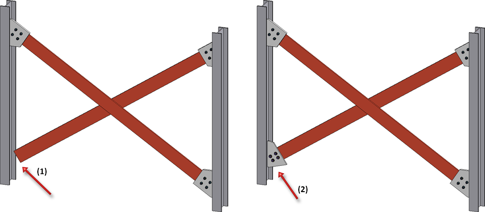
(1) Cross-bracing without plates at connection A, (2) subsequently inserted gusset plate
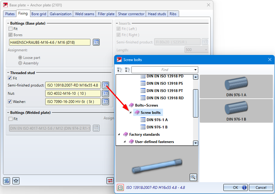
Base plate + Anchor plate (2101)
For fastening the anchor plate with screw bolts, it is now also possible to select screw bolts according to DIN 976-1A and 1B.
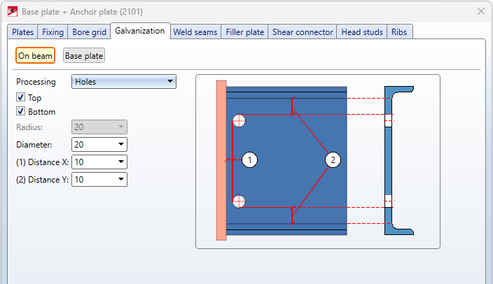
Connections- Galvanization holes on beam
In the settings for the galvanisation holes on the beam, the Y-distance of the holes now refers to the fillet on the beam and not to the flange as before. This affects the following connections:
- Base plate + Anchor plate (2101),
- End plate (2102),
- Purlin joint, 2 plates with m itre cut acc. to DAST IH (2201) and
- Beam to web, with 2 plates + stiffener (1211).
Civil Engineering - Part type catalogue 3-D
The function Civil Engineering - Part type catalogue > 3-D in the Civil Engineering functions docking window at Steel Engineering > Civil Engineering, general contains functions that have been replaced by new developments in the meantime and are therefore no longer needed.
In a first step, the entries under
- Sheet Metal Processing,
- Mechanical constructions,
- Metal Engineering / Facade Engineering and
- Steel Engineering
have been removed. However, the structure of the part type catalogue will be retained for the time being so that customer-specific catalogue entries in the above-mentioned areas can continue to be used after a HiCAD update.
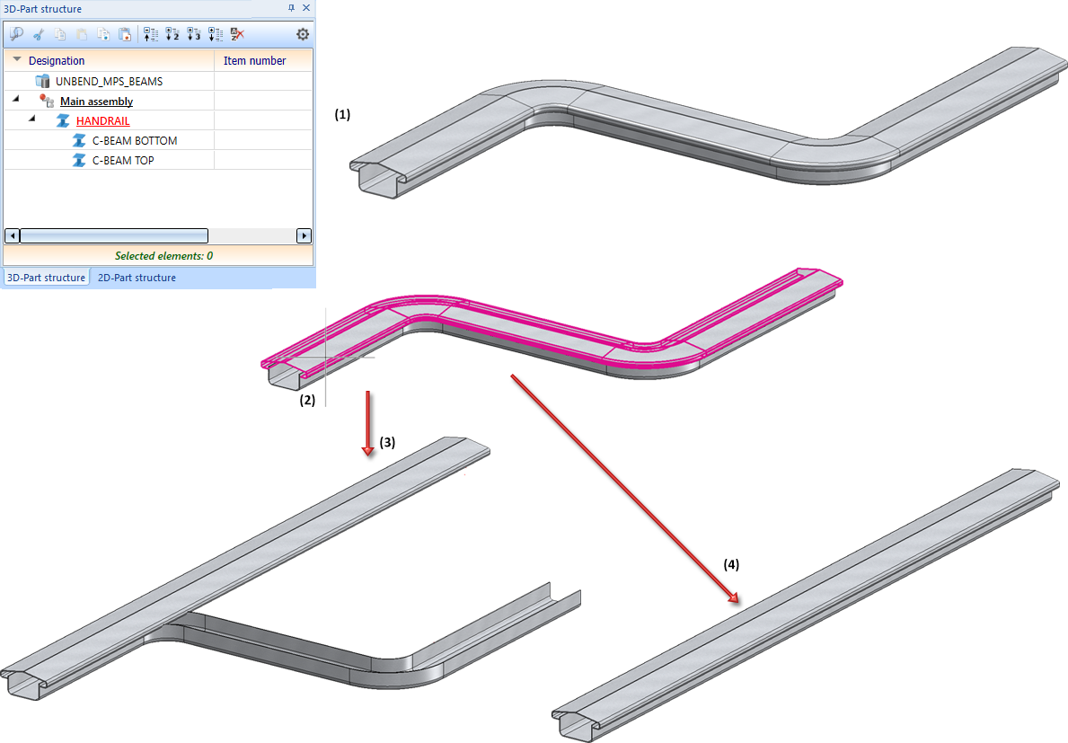
Unbending multi-part standard beams
The function Unbend beam  has been changed for multi-part beams. Previously, when a sub-beam was selected, only this beam was processed. As of HiCAD 2024, the entire multi-part beam is processed.
An example:
In the image below, the series beam ISD Handrail has been moved along a sketch (1). This has created a multi-part beam. Subsequently, the Unbend beam function was called and the upper sub-beam (2) was selected. (3) shows the result before HiCAD 2024, (4) the current result.
Parameter configuration
The default settings of the standard template for Steel / Metal Engineering have changed with HiCAD 2024. This affects the settings at Modelling > Part properties in the Configuration Editor.
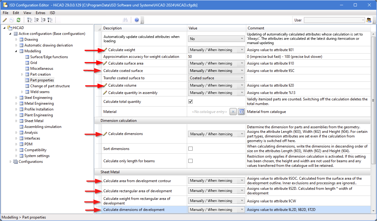
The default setting of the parameters indicated in the image below was previously Always.
The default template can be selected either during installation or subsequently with the tool ParKonfigComp.exe (or ParKonfigUser.exe).
Feature when inserting Rectangular plates
In the dialogue window of the Rectangular plate  function, the Feature checkbox is no longer available as of HiCAD 2024. This means that a corresponding feature is now always generated when plates are created.
Railing Configurator
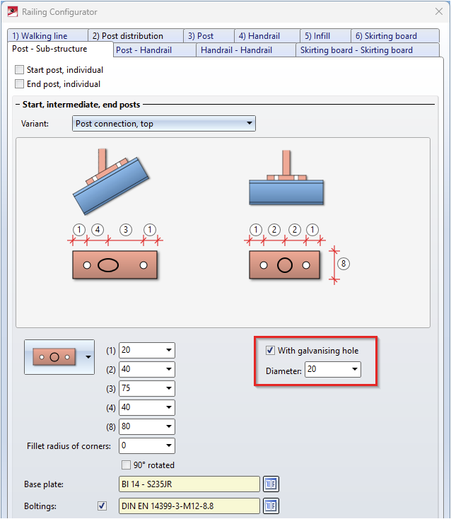
Post connection top, with galvanising hole
If the Post connection, top variant is selected for fastening the railing posts to the beam, then as of HiCAD 2024 the base plate can be provided with a galvanising hole. The Post - Sub-structure tab has been extended for this purpose.
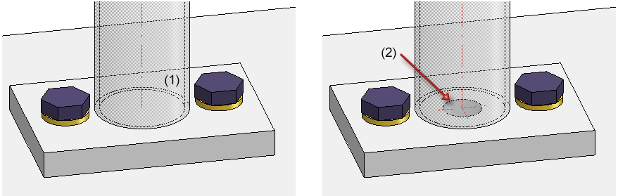
(1) without, (2) with galvanising hole
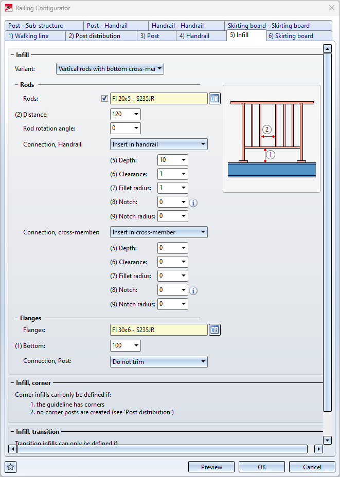
Infill with bottom cross-member - Insert filling rods
For infills with bottom cross-members it is now also possible to insert the filling rods in handrail or cross-member. Two new variants are available for this purpose:
- Insert in handrail and
- Insert in cross-member.
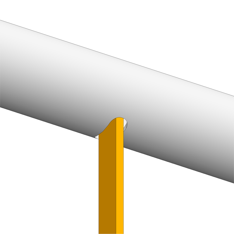
Filling rod, inserted in handrail
Post-Handrail - Wall console (prefabricated part)
The variant Wall console (prefabricated part) has been replaced by a new variant in which the screws and threads for mounting to the handrail can now also be installed.
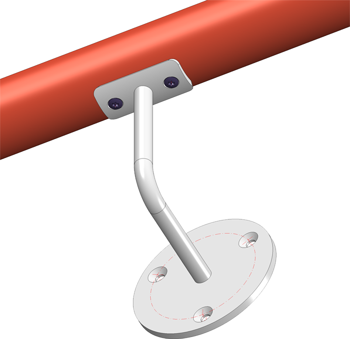
The following has been preset for the bores on the prefabricated element:
- Bores for handrail mounting: Countersink DIN 66, size 5
- Bores for wall mounting: Countersink DIN 74-1 F, size 6
If you want to preset other drillings, you can do this by changing the table Factory standards > Purchased/Factory standard parts > Railing > Wall consoles > Prefabricated brackets (RAILING_BRACKET_29_ISD.IPT). There you have to change the columns
- CS_CAT_ITEM (Bore for handrail mounting) and
- W_CAT_ITEM (Bore for wall mounting)
accordingly.
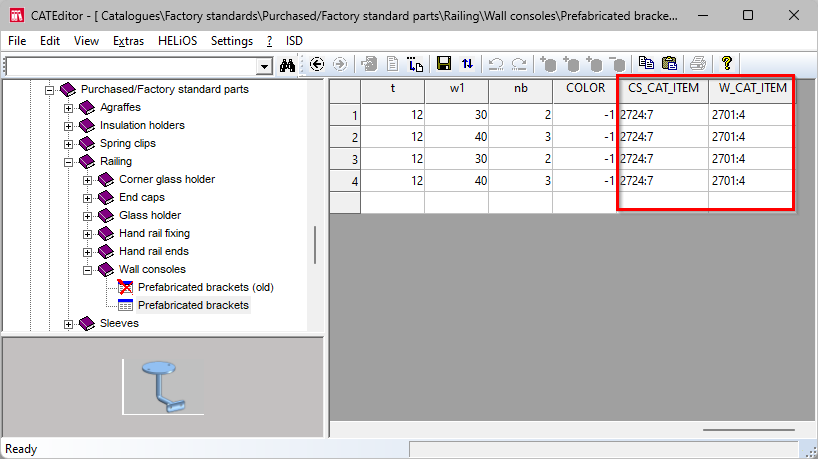
The first value in each case is the table ID, the second value is the ID of the corresponding data record. The two values are separated by a colon. For example, 2724:7 stands for the table DIN 66 at Processings, general > Processing> Countersink and the data record with the ID 7. If you double-click with the cursor in one of the columns, you can directly select the desired table and data record.
Usage for railing segments
In the automatic drawing derivation, the usage RAILINGSEGMENT has been used up to now for the dimensioning of railing segments created by the railing configurator. However, there is often the wish to dimension the railing segments differently for different railing types, for example, for segments with glass infill or segments with knee rail infill, etc.
From HiCAD 2024 this is now possible. For this purpose, corresponding usages must be defined and associated configurations created whose name contains the expression RAILINGSEGMENT, e.g. GLASS_RAILINGSEGMENT or KNEEL_RAILINGSEGMENT.
Proceed as follows:
- You define the desired usages with the Catalogue Editor at Factory standards > Usage > Civil Engineering > Steel Engineering > Railing, e.g.
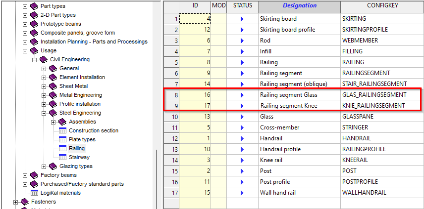
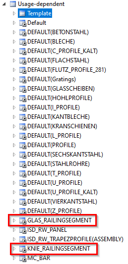
- In the Configuration Manager, you derive the new usages GLAS_RAILINGSEGMENT and KNIE_RAILINGSEGMENT from the usage RAILINGSEGMENT, for example, at Automatic drawing derivation > Production drawing > Usage-dependent. (The names must correspond to the entry in the CONFIGKEY column of the above table in the Catalogue Editor). To derive, right-click on Template and select Derive structure. Instead of _MASTER_, enter the name of the new usage, e.g. GLAS_RAILINGSEGMENT, activate the checkbox Copy values and select RAILINGSEGMENT as the template.
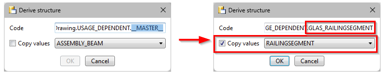
- With OK, the new usage is created.
- The new usages must now be assigned. To do this, open the entry Usage assignment, activate a row in the Railing area and click on New. A new rowis created. In the column, select the name of the usage in the selection list, e.g. Railing segment Glass, in the second column the part type and in the third column the name of the template, e.g. GLAS_RAILINGSEGMENT.Now you can define the dimensioning rules for the new types of use in HiCAD with the dimensioning rule editor. To do this, open the corresponding templates, e.g. GLAS_RAILINGSEGMENT, adjust the dimensioning rules accordingly and save the template..
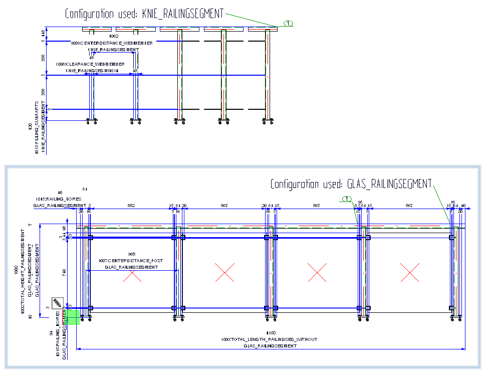
During automatic drawing derivation, these templates are then taken into account for the railing segments to which you have assigned the corresponding usage, e.g. 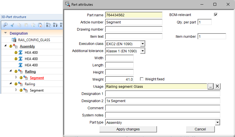
A simple example:
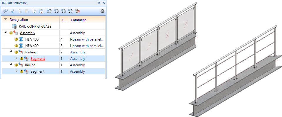
Based on the above procedure, two new usages Railing segment Glass and Railing segment Knee as well as the corresponding templates GLAS_RAILINGSEGMENT and KNIE_RAILINGSSEGMENT have been defined. The dimensioning rule sets of these templates were changed and differed.
The example construction contains two railing segments - one with knee rails and one with a glass infill. The corresponding new usages were assigned to these segments.
Example of an automatic drawing derivation
.
Extension of the BOM template for Steel Engineering
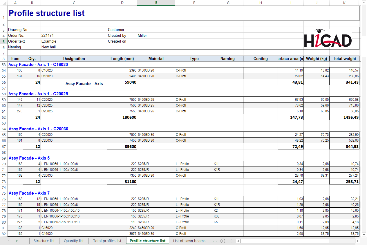
The Excel BOM template for Steel Engineering, HiCAD_Stahlbau.DE.2900.0.xlsx, has been extended. An additional sheet Profile structure list is now available. On this sheet, the parts/beams/profiles of the same type are combined and output in a structure list. The profile structure list is a mixture of structure and total profiles list and is ideal for combining steel engineering and profile installation, e.g. for hall construction and industrial facades.
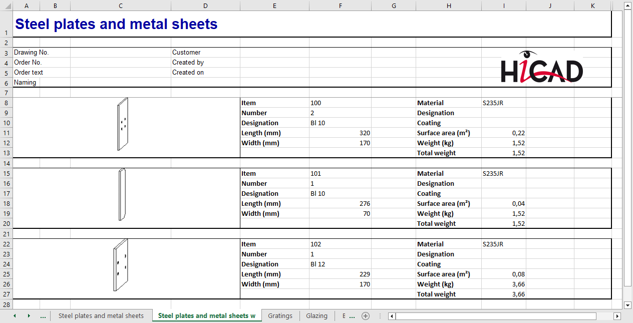
Also new is the Excel sheet Steel plates and metal sheets with image:
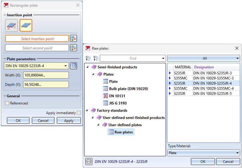
User-defined tables with Steel Engineering plates
At Factory standards > User-defined semi-finished products > User-defined plates you now have the possibility to create tables with your own steel plates. These tables are then also offered for selection via the function Steel Engineering > Plate, new > Rectangular plate .
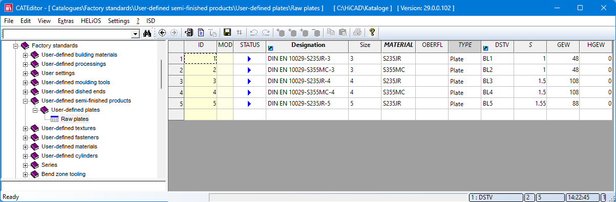
Simply copy a suitable table from the catalogue Semi-finished products > Plates into the catalogue Factory standards > User-defined semi-finished products > User-defined plates and edit it.
