Function call and dialogue window
Steel Engineering > New > Beam 
With this function, 3-D standard beams and profiles, multi-part standard beams, prototype beams and elongated plates can now be inserted. The selection is made in the following catalogues:
- Semi-finished products > Plates,
- Semi-finished products > Cold rolled sections,
- Semi-finished products > Beams + Profiles,
- Factory standards > Multi-part standard beams,
- Factory standards > Series
- Factory standards > Prototype beams and
- Factory standards > Factory beams.
In addition, you have the option to insert configurable prototype beams.
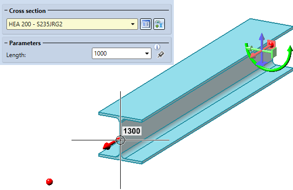
The insertion of the beams and profiles takes places via the dialogue window shown below.
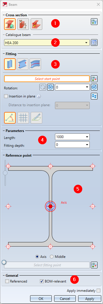
There you select the desired cross section and enter the required parameters such as the Length of the beam, the angle of rotation or the direction. Which parameters have to be specified explicitly depends on the selected fitting type and the selected sourcen.
The dialogue window consists of the following areas:
- Cross-section
- Catalogue beam/Prototype beams/Sketch beamross section / Prototype beams
- Fitting
- Parameters
- Reference point
- General
|
Insert beam or profile in the drawing |
|
|---|---|
|
Apply immediately |
If this checkbox is active, the beam is immediately adopted after entering the parameters required for the selected installation type. Corrections, e.g. changing the length or the angle of rotation, are then no longer possible for this beam in the dialogue. The dialogue window remains open so that you can directly insert further beams. |
|
OK |
The beam is inserted as shown in the preview and the dialogue window is closed. |
|
Apply |
The beam is inserted. In contrast to OK, the dialogue window remains open so that you can insert further beams directly.. |
|
Cancel |
The function is terminated without inserting the beam. |
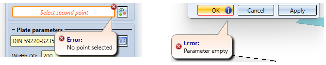
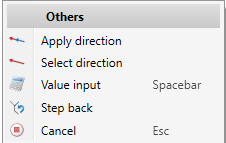
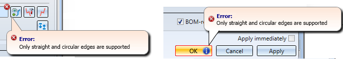
Incorrect or missing entries are indicated in the dialogue with the  symbol at the input field , and the
  symbol at the OK button. If you move the cursor over the symbol, a corresponding message is displayed, e.g.
![]() Please note:
Please note:
- As soon as you have entered the required parameters, a preview of the beam is displayed. You can change the parameters as long as you have not yet accepted the beam displayed in the preview.
- If you right-click in a value input field, a context menu opens with whose functions you can, among other things, transfer angles and lengths from existing drawing objects into the input field.
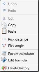
For example, you can use the Pick distance function to transfer a beam length from the drawing. Or you want to take over the angle of rotation for the beam from the drawing, then use the function Pick angle.
Please also read the general notes on Elongated Plates and Multi-Part Standard Beams in the same-named topics.

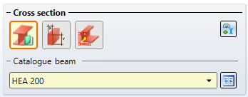
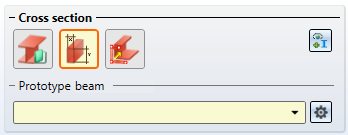
Cross-section
Under Cross-section, you determine whether a beam or profile from the HiCAD catalogue or a configurable prototype beam is to be inserted.
|
|
Via catalogue... Use this option to insert a beam or profile from the above-mentioned catalogues under Semi-finished products or Factory standards. To do this, select the part in the corresponding catalogue in the Cross-section area after clicking on the
|
|
|
Prototype beams can be inserted with this option. Prototype beams have a fixed geometry. Examples are I-, L- and U-beams. In contrast to standard beams, you can select the dimensions individually and variably here. In addition, you can save prototype beams with the dimensions you have changed in catalogues and use them again at any time.
To select and configure a prototype beam, click on the |
|
|
This function derives a beam or profile from an existing sketch in the drawing. Multi-part sketches are also allowed.
|


Alternatively, you can also select a beam that already exists in the drawing as a Reference beam. To do this, click on the  symbol and select the reference beam.
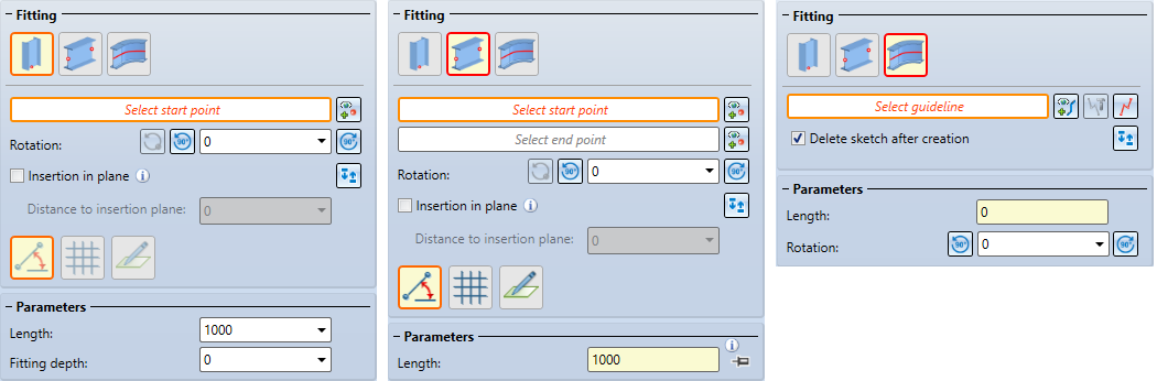
Fitting and Parameters
Under Fitting, the following types of insertion for beams are available:
 Insertion perpendicular to processing plane
The actions and parameters required for fitting depend on the type of fitting that was selected.
|
Actions / Parameters |
Fitting |
||||||
|---|---|---|---|---|---|---|---|
|
|
|
|
|||||
|
Select start point After selecting the point, Point is displayed in the dialogue window. If you want to change the start point, click on the |
|
|
|
||||
|
Select end point see start point |
|
|
|
||||
|
Select guideline Here you select a planar sketch or a 3-D sketch as guideline. The beam is installed along this guideline. |
|
|
|
||||
|
Rotation The beam is rotated around the beam axis by the specified angle .
|
|
|
|
||||
|
|
|
|
||||
|
Switch ends Click on the symbol to mirror the beam to be inserted (useful e.g. for L-beams). |
|
|
|
||||
|
Insertion in plane If this checkbox is active, all selected points are projected into the current working plane. The beam is then inserted in such a way that the projection of the start point from the selected reference point of the beam has the specified distance to the insertion plane. |
|
|
|
||||
|
Length |
|
|
|
||||
|
Width of elongated plate only if an elongated plate from the catalogue Semi-finished products > Plates > Plate is selected as the cross-section. |
|
|
|
||||
|
Fitting depth The fitting depth is the distance from the starting point of the beam to the selected starting point. The actual beam length is then the sum of the length and fitting depth. |
|
|
|
||||


Insertion perpendicular to processing plane
The insertion takes place perpendicular to the current processing plane in the Z-direction. If no processing plane is available, the XY-plane of the world coordinate system is used.
- Select the start point.
- If the beam is to be rotated around the beam axis, enter the angle or select one of the rotation functions
 or .
or . .
. - If the start and end points are to be switched, click on the
 . symbol.
 - Enter the Length of the beam and - if desired - the Fitting depth. The actual beam length is then the sum of Length and Fitting depth.
- If the checkbox Insertion in plane is active, the start point is projected into the current processing plane and the beam is inserted perpendicular to this point - taking into account the value entered for Distance to insertion plane.
- As long as you have not yet adopted the beam, you can rotate it dynamically with the cursor by clicking on
 .
.
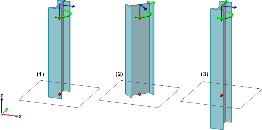
(1) Length only, (2) Length and Angle 45°, (3) Length + Fitting depth
(1) Insertion of an L-profile, (2) Insertion with switching of start and end point
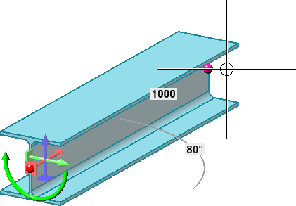
Insertion via 2 points 
Here the insertion is done by selecting two points. The position of the beam is defined by the start point. The end point determines length and direction.
- Select the start point. HiCAD displays a plane preview at the start point, which represents the current coordinate system. The drawing plane is parallel to the processing plane active when the function is called or to the XY-plane of the world coordinate system and runs through the start point. As with the sketching technique, you can now determine the end point as follows:
|
|
Angle + Distance In this mode (default setting), the angle and the distance to the start point are displayed at the cursor. To determine the end point, place the cursor at the desired position and drop it with a left-click.
The values for the distance and angle grid can be preset in the Configuration Editor at System settings > Identification in the Grid section. |
|
|
XY-grid The X- and Y- distance to the start point are displayed. To determine the end point, place the cursor at the desired position and drop it with a left-click. |
|
|
Free In this mode you can draw freely, i.e. without a grid. The X- and Y-distances to the start point are displayed on the cursor. To determine the next point, place the cursor at the desired position and drop it with a left-click.
|


 Points determined in this mode always lie in the current processing plane.
To determine the length and direction of the beam, there are three possibilities.
- Identify the end point with the cursor.
- Take over the length and direction of the last beam with a right-click. The prerequisite is that you have not left the function in the meantime.
- Determine the end point with another point option, e.g. Relative R.
By default, the length is determined by the distance between the two points. A special feature here, however, is the possibility to switch the type of length determination. The buttons  or
or  are available for this purpose.
|
|
With this setting, the length is automatically determined by the distance between the start and end points. The Length field is then greyed out. This is the default setting. |
|
|
If this setting is active, the end point only determines the direction of the beam. The beam length is determined by the value entered in the Length field. In addition, the direction is shown in the drawing by an arrow. By dragging this arrow with the cursor, the length can also be changed.
|
If the checkbox Insertion in plane is active, the beam is installed in such a way that the selected reference point has the specified distance to the insertion plane. The beam axis runs parallel to the plane.
Insertion along guideline 
Here you insert beams along a guideline. This can be a planar sketch or a 3-D sketch. The beams of the selected type will be placed on the lines of the sketch. The individual beams are mitred or curved depending on the sketch.
Select the desired guideline in the drawing.
The following options are also available for selection:
|
|
Select guideline Click on the symbol to select another sketch as the guideline. |
|
|
Process sketch With this function you can process a previously selected sketch. For this purpose the Process sketch dialogue window is displayed. Modify the sketch as desired and then click Apply sketch in the dialogue window. The dialogue will continue with the modified sketch |
|
|
New sketch in plane With this function you can create a new sketch. Draw the desired sketch and then click Apply sketch. The dialogue continues with the new sketch. |


In the following image, an L-beam on a plane sketch is shown on the left, once without and once with the ends switched. On the right, an L-beam has been placed on a 3-D sketch.
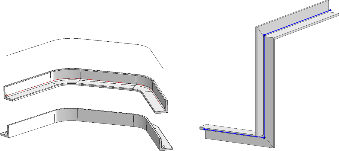
- The selected guideline may only consist of straight and circular lines, other elements such as ellipses or B-spline edges are not allowed. The lines of the sketch must not intersect or lie on top of each other and no more than 2 lines may converge in one point. If the sketch selected as a guideline does not meet the necessary requirements, this is indicated by the symbol at the input fileld(s) and by the symbol at the OK button, e.g.
- Not all beam processing functions can be applied to beams that are inserted along guidelines.
-
For beams that are installed along a composite edge, the following must be taken into account for the functions Change length and Change beam length, via new total length: If there is an circular arc at the beam end of the composite edge to be extended, the value of the extension or the total length is the arc length of the extension. For straight beam ends, it is the value of the straight extension. This means that along a composite edge it is also possible to extend it directly without having to load the guideline (in the Feature), extend it and then replace it.
Reference point
The reference point determines the orientation of the beam in the coordinate system and is also taken into account when exchanging beams.
The Centroid of the beam cross-section is preset.
|
|
a Top left, b Top axis, c Top right d Axis left, e Centre of gravity, f Axis right g Bottom left, h Bottom axis, i Bottom right |
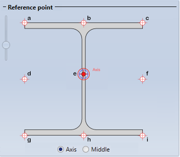
The left slider can be used to zoom the reference point display.
Instead of the Centroid, the Middle (area cross-section) of the bounding box, i.e. the smallest cuboid that completely encloses the beam, can also be used. However, this only has an effect on asymmetrical beams, for example L-beams.
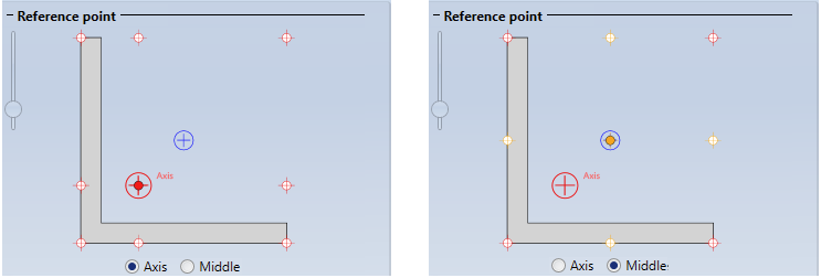
If another of the predefined reference points is to be used, simply click on the corresponding point symbol in the dialogue window.
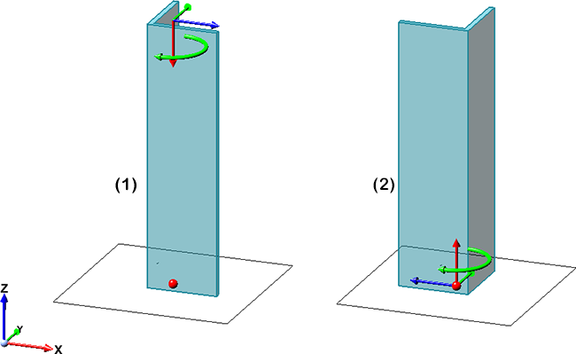
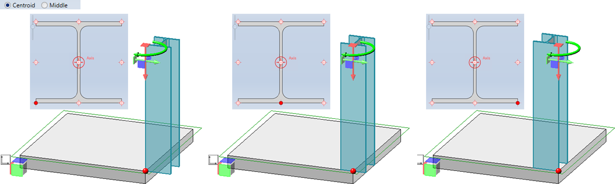
The following image shows the alignment with different reference points. The red point in the preview is the start point.
You can also select a fitting point as an insertion aid. However, this is not possible if beams are placed along a sketch.
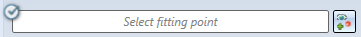
To do this, activate the option and then click on the  symbol. HiCAD displays a preview of the beam cross-section. Then select the desired fitting point. This point is then the insertion point of the beam. This does not change the selected reference point. If the option is activated and no fitting point is determined, the centre of gravity of the beam is used as the insertion point.
In the image below the insertion without fitting point is shown on the left. On the right, the centre of the lower left fillet has been selected as the fitting point.
General
In this area you can determine by activating/deactivating the corresponding checkboxes
- whether the part should be referenced and
- whether the part should be BOM-relevant.
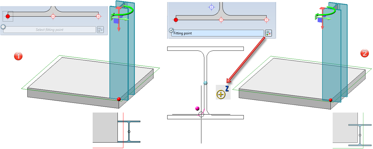
Configure prototype beams
To select and configure a prototype beam, click the  icon in the Prototype beams area. The dialogue window for configuring prototyped parts is displayed. Here you have the option of using existing prototype beams as a basis and incorporating them with individual dimensions, saving new prototype beams in the catalogue or loading existing prototype beams.
Self-defined prototype beams can be saved in the catalogue Factory standards > Prototype beams. For this purpose, the sub-catalogues for the various prototype beams already contain empty templates for tables, e.g. EXAMPLE_TAB-I for I-beams. These files (.IPT) can be found in the HiCAD folder Kataloge/Werksnormen (Catalogues/Factory standards). To create new table files or edit existing table files, you can use the Catalogue Editor. There you can also define your own catalogues.
- In the Prototype beams dialogue window, select the desired beam type in the corresponding list box.
- Enter the name of the new prototype beam in the Designation field.
- Enter the values for the dimensions, e.g. height, radius, etc..
- Select the Material to be assigned to the beam. When the function is called up for the first time within a HiCAD session, S235JRG2 is preset as the material; when the function is called up again, the material selected last is preset.
- Activate the checkboxes Weight per length, Commercial weight per length and Surface area per length if you want to change the displayed default value.
- To insert the beam with the displayed values, exit the dialogue window with Close. Remember to save the beam - if desired - beforehand by clicking on
 .
.
You also have the option of loading an existing prototype beam as a template and adjusting the parameters accordingly.
Loading a prototype beam from a catalogue as a template
To load an existing prototype beam from a catalogue, proceed as follows:
- Click on
 .
. - Select the desired beam type and the table file.
-
The data of the selected beam is displayed. You can then fit the beam with the current data or correct the displayed data. Remember to save the beam with the changed data if necessary!
-
Select the Fitting type and specify the corresponding parameters.
Saving a prototype beam in the catalogue
To save a prototype beam with the settings displayed in the dialogue window, proceed as follows:
- Click on.
- Select the beam type, e.g. I-beam, and then the table file in which you want to save the beam, e.g. EXAMPLE TAB-I.I.
-
The data of the beam is displayed. You can correct these data if required.
- Save the beam with OK.
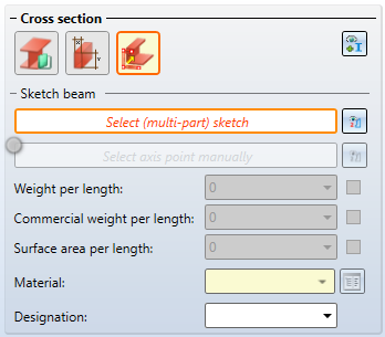
Beam from (multi-part) sketch
This function derives a beam from any sketch existing in the current drawing. The sketch can also be a multi-pat sketch.
Simple sketch
Create the required sketch. Please note that the sketch must be continuous and that the distance of the sketch to the coordinate system is decisive for the later position of the inserted beam. The beam is inserted at the same distance from the xy plane as the sketch is from the origin of the coordinate system. HiCAD always automatically places the beam axis in the coordinate origin. However, you also have the option of determining the position of the beam axis manually, by specifying a 3-D point.
Proceed as follows:
-
After calling up the function, select the corresponding sketch. If a sketch is active when the function is called up, this sketch is preset. To change the selection, click on the
 symbol and select the desired sketch.
 -
HiCAD normally determines the position of the beam axis automatically (see above). If you want to determine the position manually, click on the
symbol and determine the desired 3-D point. If you always want the axis point to be determined automatically, you can also deactivate the field. 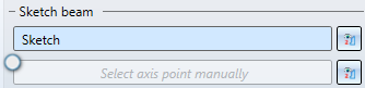
-
If you want to assign additional data to the beam (Weight per length, Commercial weight per length, Surface area per length), activate the corresponding checkbox and enter the value.
-
Select the material in the catalogue. To do this, click on the
 symbol.
 -
Enter the article number of the beam in the Designation field or choose it from the selection box.
-
Select the type of insertion under Fitting and define the corresponding parameters.
Beam derived from a sketch (left); (1) Point for beam axis
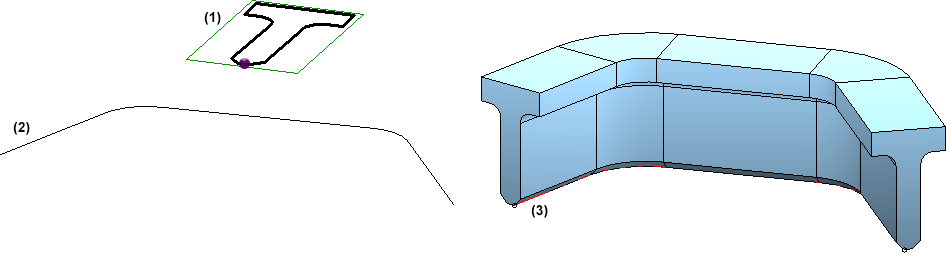
Beam (3) derived from a sketch (1) and routed along a sketch (2)
![]() Please note:
Please note:
- The cross-section of a beam derived from a sketch can be subsequently changed using feature technology. The sketch is entered in the feature log and can be loaded and processed there.
- In contrast to the other structural steel engineering beams, beams derived from a sketch can also have a point displacement in the rectangle transverse to the beam axis.
- Alternatively, you can also use the Beam from sketch (3-D SE) function in the context menu of the sketch to create the beam. Please note the following: If the sketch belongs to an assembly, the beam is also assigned to this assembly.
Multi-part sketch
The creation of a beam from a multi-part sketch is largely similar to simple sketches. However, the following conditions must be observed:
Each closed element must be a separate sketch. If there are several sketches, these must be subordinated to a 3-D dummy part. Sketches with branchings must also be subordinated to a 3-D dummy part. Sketches with self-intersections are not permitted.
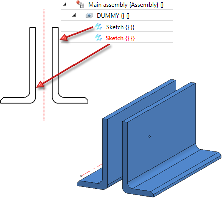
Multi-part beam derived from a dummy part with two sketches (left)

Further information
Standard beams
Display of beam orientation
When inserting Steel Engineering beams and profiles, the orientation of the parts is displayed graphically as a coordinate system, i.e.
- axis direction (in the special colour X-axis),
- up/down (in the special colour Z-axis),
- left/right (in the special colour Y-axis),
- direction of rotation
at the start of the beam. The display occurs when the beam is visible and its position can still be changed.
When the beam orientation is to be displayed can be set in the Configuration Editor at System settings > Visualisation > Indicate orientation of active Steel Engineering beam.
- Only upon insertion
The orientation is only displayed when beams are installed. This is the default setting. - Always
The orientation is always displayed. - Switch on/off with F6 key
The orientation can be shown/hidden with the F6 key. Alternatively, you can use the button
 Show beam orientation or drawing orientation of the active 3-D part
on the Coordinate system toolbar (at the bottom of the HiCAD dialogue).
Please note that the size of the orientation symbol does not change when zooming.
(1) Display when activating, (2) Display during insertion
When the beam orientation is to be displayed can be set in the Configuration Editor at System settings > Visualisation > Indicate orientation of active Steel Engineering beam.
The colours of the orientation symbol can be changed with the Colour Editor at Drawing > Others.
When inserting catalogue standard parts and semi-finished products (Steel Engineering beams and plates) in HiCAD, the corresponding part attributes are partially assigned values from the catalogue entry. (e.g. the BZ (Designation) column is transferred to the "Article number" part attribute). This assignment is freely configurable. For this purpose, it is possible to link a table column with a part attribute in the catalogue tables. If a part from this table is inserted in HiCAD, the value of the linked column is transferred to the part attribute. For example, a user can enter the article number and/or supplier in a column, whereby the value can be transferred to a part attribute during part insertion and used for part annotation or bill of materials. In the catalogue table (see Catalogue Editor), a link symbol is displayed in the column header for linked columns.In all HiCAD standard tables for standard parts+semi-finished products, the column "BZ" (Designation) is linked with the part attribute "$BB".
Please also read the notes on automatic dimension calculation.
Series beams
For series beams, which you load from the catalogue FACTORY STANDARDS > SERIES, the user-specific attributes CUSTOM1 and CUSTOM2 are also evaluated. These can be used, for example, for interfaces to ERP systems (Enterprise Resource Management Systems)..
Multi-part standard beams
- Multi-part standard beams are managed via the Catalogue Editor. Various tables are predefined in the catalogue Factory standards > Multi-part standard beams. If you want to create your own tables for your multipart beams or plates, use the corresponding functions of the catalogue editor. You can find out more about this in the online help of the Catalogue Editor (cateditor.exe).
- To add more multi-part standard beams to the selection catalogue, choose Further functions > Settings
 > Define and save as catalogue part.
Prototype beams
When inserting a prototype beam, an article master assigned to the prototype beam in the Catalogue Editor will not be taken over!
