Civil Engineering functions docking window > Steel Engineering > Connections > Web/flange to web/flange > Gusset plate (2510) 
With this variant, any beam can be connected with one to three other beams by means of a gusset plate connection - as is often the case in hall construction.
The beams to be connected must meet the following criteria:
- The beams must be of the type steel tube, hollow section, L-beam, round or flat steel.
- In the case of hollow profiles, steel tubes and round steel bars, the X-axes of the beams must lie in one plane. This plane must intersect the connection profile at a planar facet and lie parallel to the X-axis of the connection beam..
- Flat steels and L-beams must have at least one common plane in which the gusset plate can lie.
- If more than one beam is connected, then all beams to be connected must have the same beam type. This means that the beams must
- all be flat steels, or
- all L-beams, or
- a mix of steel pipes, hollow profiles and round steels.
The connection of an L-beam and a steel pipe, for example, is not possible.
The connection consists of a gusset plate, the connection plates between gusset plate and beam to be connected and - optionally - the bolting between gusset plate and connection plate. Gusset plates are steel plates, the connecting plates can be of the flat steels or steel plate type.
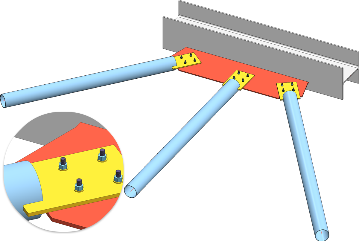
Gusset plate connection with three steel pipes
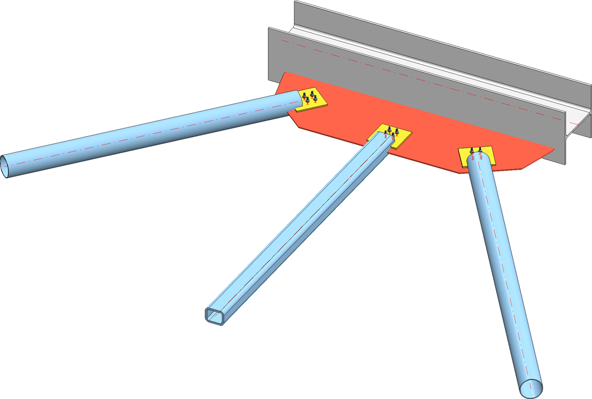
Gusset plate connection with two steel pipes and one hollow profile
If the beam to be connected is of the flat steels or L-beam type, then no connection plates are created.
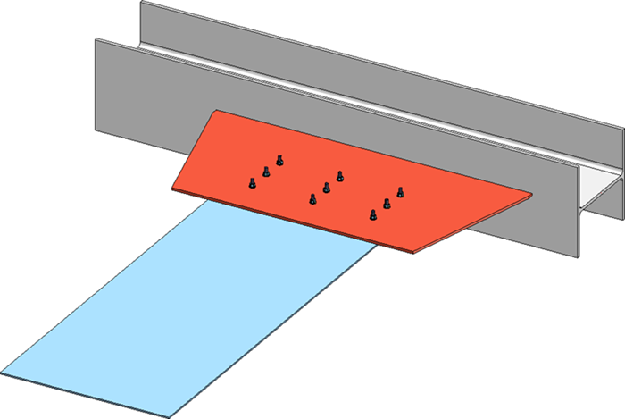
Connection of one flat steel
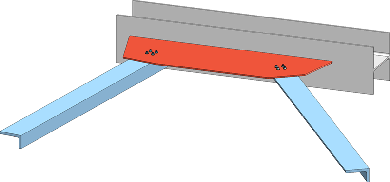
Connection of two L-beams
Tabs
The configuration of the connection is done via the following tabs:
 Favourites
The settings of the dialogue can be saved as favourites and reused later. To do this, click on thel symbol at the bottom left to activate the context menu. More about favourites management can be found in the Manage Favourites topic of the HiCAD Basics help.
Buttons
|
Preview |
When the dialogue window is open, you can use the Preview button to display a preview of the gusset plate created by the current settings. You can also enlarge and reduce the image with the zoom functions. |
|
OK |
Start the generation of the gusset plate with OK. The status of the generation is indicated by a progress bar in the status bar. After successful generation the dialogue window will be closed. |
|
Cancel |
Cancel closes the dialogue window without generating the gusset plate. |

Beams + Profiles
On this tab you determine
-
the connection beam and
- the beams to be connected.
First select the connection beam. A usage type can be selected from the catalogue for the assembly of this beam. If a usage type is already assigned to the assembly, you can use the checkbox Overwrite usage to determine whether this usage should be retained or replaced by the usage type selected here.
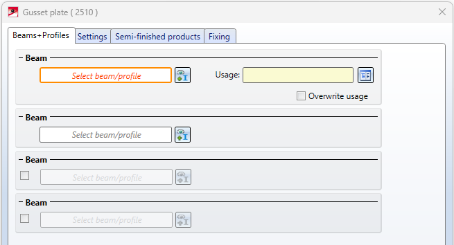
Then select the first beam to be connected. If you want to connect a second and third beam, activate the corresponding checkbox and then select the desired beam in the drawing.
The beam selection can be corrected by clicking on  and then selecting the desired beam.
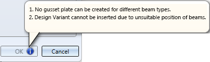
If it is not possible to install the connection with the currently selected beams, the  symbol is displayed on the OK button and - if you point to this symbol with the cursor - a corresponding error message is displayed.
As soon as you have selected the first beam to be connected, the connection is visualised graphically on the basis of the current settings on the tabs as follows:
| blue |
Gusset plates |
|
red |
Connecting plates |
|
green line |
Line to which beams to be connected are trimmed |
|
green points |
Bore grid |
|
blue arrows |
Fitting direction |
In addition, the number of the beams to be connected is displayed and it is indicated where the top and bottom are.

Settings
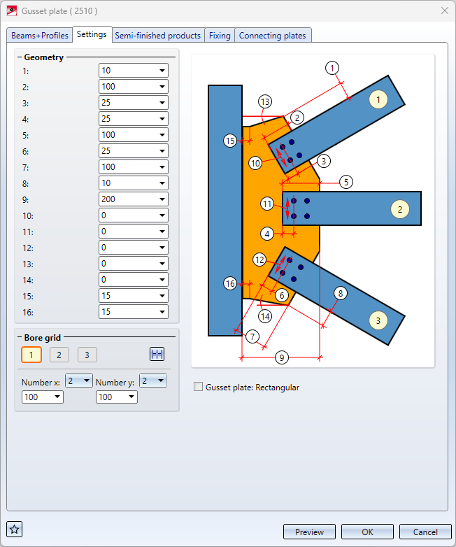
In this area you determine the size of the gusset plate and the alignment of the connection plates to the gusset plate. In addition, you define the bore grid here. You determine the size of the connection plates on the Connecting plates tab.
If you want to insert rectangular gussets, activate the corresponding checkbox.
- Settings for 1 connection beam
- Settings for 2 connection beams
- Settings for 3 connection beams
- Bore grid
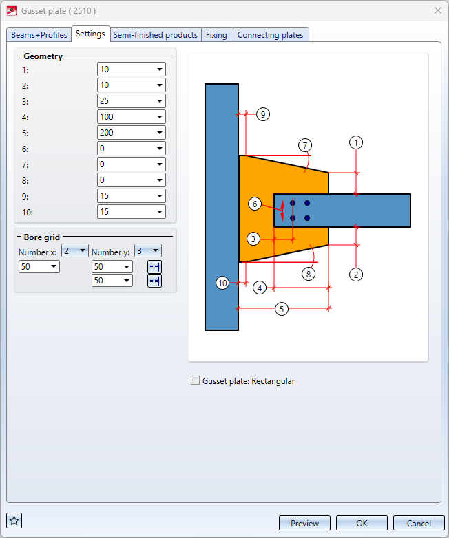
Settings for 1 connection beam
|
1, 2 |
Distance between the corner of the gusset plate and the outer edge of the connecting plate |
|
3 |
Distance between the installation edge of the connecting plate and the first line of the respective bore grid (centre of bore) |
|
4 |
Distance between the installation edge of the connecting plate and the edge of the gusset plate |
|
5 |
Width of the gusset plate |
|
6 |
Offset of the bore pattern in relation to the centre of the beam |
|
7, 8* |
Angle of the left and right gusset plate edges to the axis of the connection beam; it can be specified as positive and negative |
|
9, 10* |
This value should be specified to avoid sharp edges that could be burnt during welding. It should be between 15 and 20. |
* not applicable for rectangular gusset plates
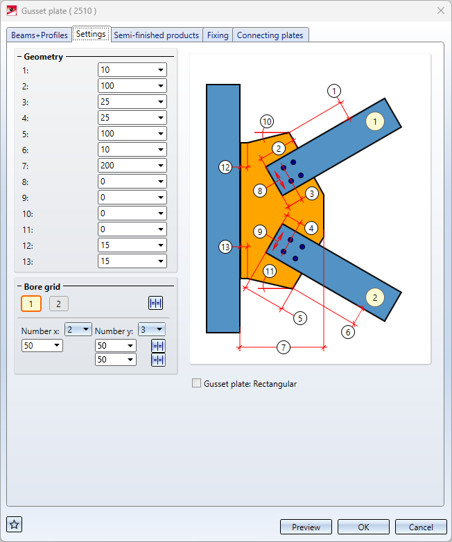
Settings for 2 connection beams
|
1, 6 |
Distance between the corner of the gusset plate and the outer edge of the connecting plates |
|
2, 5 |
Distance between the installation edge of the connecting plates and the edge of the gusset plate |
|
3, 4 |
Distance between the installation edge of the connecting plates and the first line of the respective bore grid (centre of bore) |
|
7 |
Width of the gusset plate |
|
8, 9 |
Offset of the bore grid in relation to the centre of the beam |
|
10, 11* |
Angle of the left and right gusset plate edges to the axis of the connection beam; it can be specified as positive and negative |
|
12, 13* |
This value should be specified to avoid sharp edges that could be burnt during welding. It should be between 15 and 20. |
* not applicable for rectangular gusset plates
Settings for 3 connection beams
|
1, 8 |
Distance between the corner of the gusset plate and the outer edge of the first or third connecting plate |
|
2, 5, 7 |
Distance between the installation edge of the connecting plates and the edge of the gusset plate |
|
3, 4, 6 |
Distance between the installation edge of the connecting plates and the first line of the respective bore grid (centre of bore) |
|
9 |
Width of the gusset plate |
|
10, 11, 12 |
Offset of the bore grid in relation to the beam centre |
|
13, 14* |
Angle of the gusset plate edges left and right to the axis of the connection beam; it can be specified as positive and negative |
|
15, 16* |
This value should be specified to avoid sharp edges that could be burnt during welding. It should be between 15 and 20. |
* not applicable for rectangular gusset plates
The bore grid determines the arrangement of the screw connection of the gusset plate and connecting plates. It can be specified individually for the connecting plates of the beams to be connected. To do this, simply click on the button with the number of the beam to be connected (1). If you want the hole pattern to apply to all beams to be connected, click on Apply to all  (2).
(2).
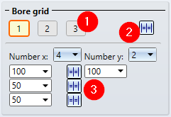
Enter the number of bores in X- and Y-direction as well as their distance to each other. If all holes in one direction are to have the same distance, you can simplify the entry. Simply enter the distance value in the input field and click on Equidistant (3) .
Semi-finished products
In this area you determine
- the semi-finished product of the gusset plate,
- the semi-finished product of the connecting plates,
- the bolting of the gusset plates and connecting plates and
- the assignment of the boltings.

By clicking on the respective  symbol, the semi-finished products can be selected directly in the corresponding standard part catalogues.
Possible semi-finished products are:
|
Standard parts |
Permissioble catalogues |
|---|---|
|
Gusset plates |
Semi-finished products > Plates |
|
Connecting plates |
Semi-finished products > Plates Semi-finished products > Profiles > Flat steel Factory standards > Factory beams > FLUTZ profiles Factory standards > Factory beams > Frankstahl > A3 Steel bars Factory standards > Factory beams > Frankstahl > C3 Stainless steel bars |
The bolting can be different for the beams to be connected. By activating / deactivating the corresponding checkboxes, you can determine whether the boltings or only the bores are to be created. By activating the checkbox Invert you can also change the direction of the bolting.
To define the boltings of the connecting plates to the gusset plates, click on the symbol and select the desired components in the Bolting dialogue window. The composition of the bolted connections is done in the same way as for the 3-D function Bolting.
If you want to use the same bolting for all connection beams, click on .
The boltings are each inserted as a bolting assembly with the name Bolting. Under Assignment you determine by activating the corresponding radio button whether these bolting assemblies are assigned to the assembly of the respective beam or inserted as a Loose part. When assigned as a loose part, the bolting assembly will be inserted as an independent assembly on the same level as the assembly of the beam.
Please note:
If the beams to be connected are of the type L-beam or flat steel, then no connecting plates are created. With L-beams, the choice of the position to the gusset plate is also omitted.
Fixing
Here you determine whether weld seams are to be created at the gusset plate and at the connecting plates. If yes, select the type of thickness designation, the weld thickness, the weld type and the inspection category. In addition, you can specify whether the connection plates are to be attached to the top or bottom of the gusset plate.
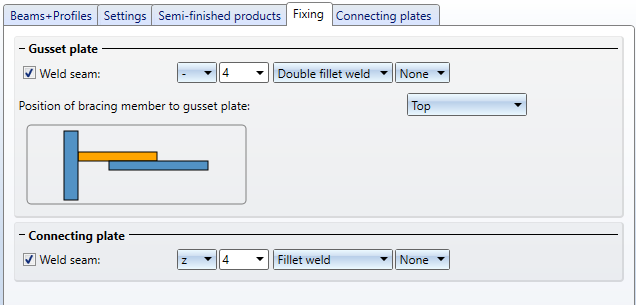
For continuous HV and HY welds, enter 0 as the weld thickness..
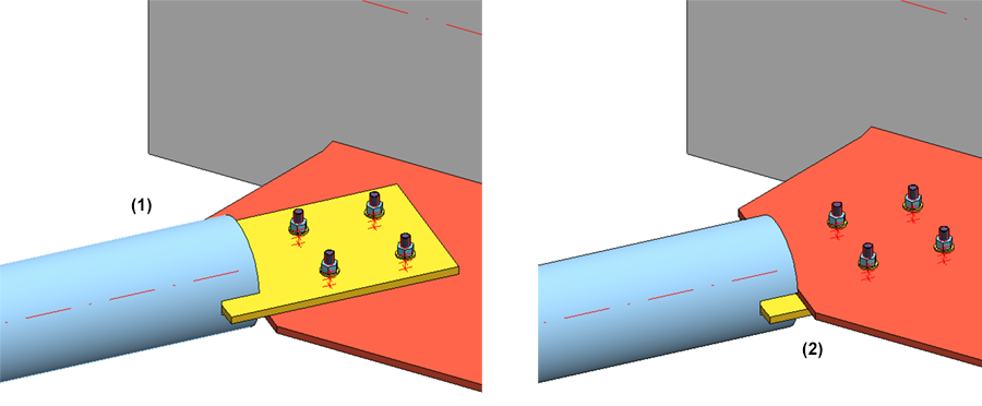
(1) Connecting plates, top- position; (2) Bottom-position
If the beams to be connected are of the L-profile or flat steel type, then no connecting plates are created. With L-beams the choice of the position to the gusset plate will also be omitted.
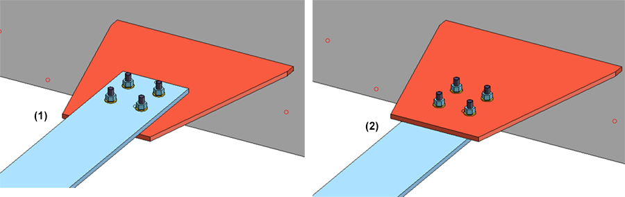
The image shows the connection of a flat steel. The connection is made directly to the gusset plate without connecting plates. (1) Top position, (2) Bottom position
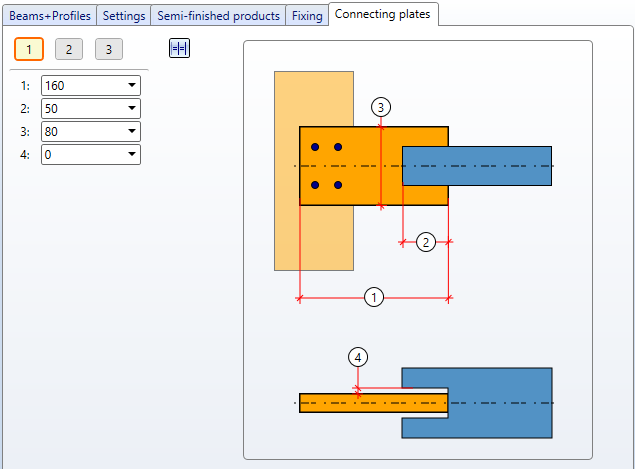
Connecting plates
Here you specify the dimensions of the connecting plates.
|
1 |
Length of the connecting plate |
|
2 |
Distance between the outer edge of the connecting plate and the installation edge of the beam to be connected |
|
3 |
Width of the connecting plate |
|
4 |
Clearance between the beam to be connected and the connecting plate |
The size of the connecting plates can be specified individually for the beams to be connected. To do this, simply click on the button with the number of the beam to be connected. If you want the settings to apply to all beams to be connected, click on Apply to all .

Connections + Variants (3-D SE) • Dialogue Window for Connections (3-D SE) • The Catalogue System for Connections+Variants (3-D SE) • Insert Connections - General Procedure (3-D SE)