Column Connection, Frame Corner
With this variant two I-beams are connected with a bolted or welded beam frame corner. You can create the frame corner with or without stiffeners, haunched plates or other components, e.g. haunched flanges, web reinforcements and reinforcement plates or filler plates. It is also possible to insert stiffeners at the column and ribs at the girder, and also weld seams as well as to apply galvanization holes.
Requirements for the creation of frame corners are as follows:
- Both beams must be the type I-beam.
- The webs of the beams must lie in one plane.
- The beam axes must not be parallel and must not lie in one straight line.
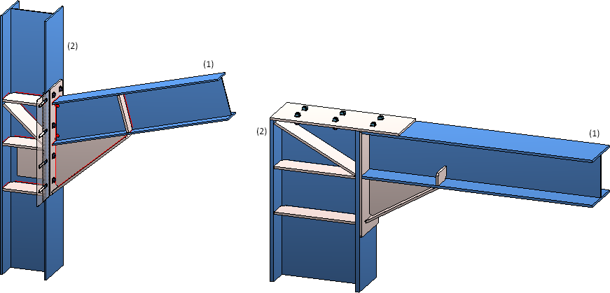
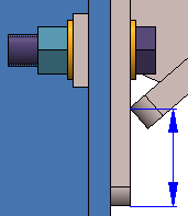
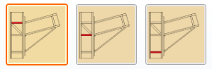
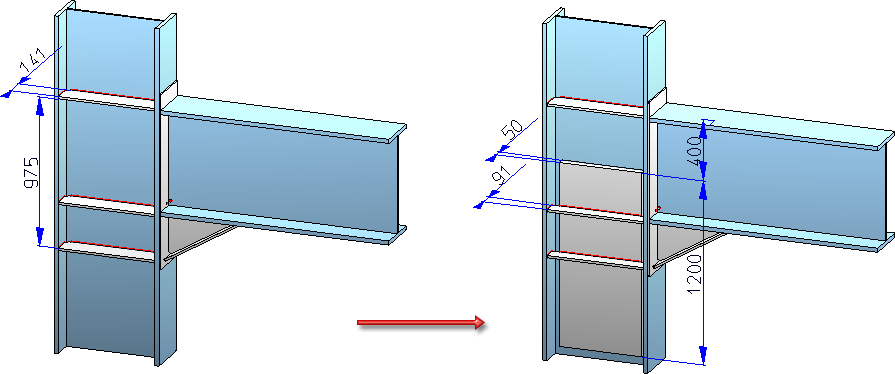
Example - (1) girder, (2) column, Left: with front plate, right: with front plate and tension plate
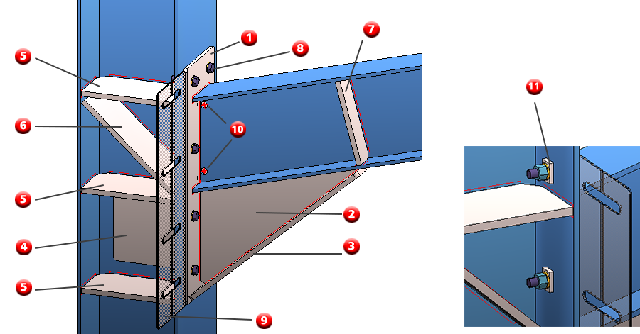
(1) Front plate, (2) haunch, (3) haunched flange, (4) web reinforcement, (5) stiffeners at column,
(6) diagonal reinforcement stiffener, (7) stiffener at girder, (8) bolting, (9) filler plates (not pre-planned),
(10) galvanization holes, (11) reinforcement plates
The Frame corner (2203) dialogue window will be displayed.
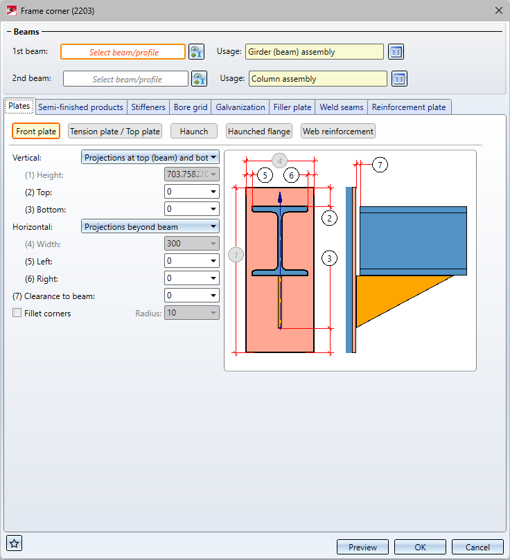
Beams:
- Identify the beam (girder) in the vicinity of the reference end.
- Identify the beam to which the first one should be connected (column).
To change the selection, click on the  symbol.
A usage type can be selected from the catalogue for each beam assembly. If a usage is already assigned to the beams' assemblies, this is displayed here.
By clicking on the Preview button you receive a preview of the connection - based on the currently entered data. If you wish to modify the data make the respective changes and once again press Preview to update the image. With OK the connection with the updated data will be installed and the dialogue window closes. If you leave the dialogue window with Cancel the function will be terminated without installing or changing the connection.
The settings in the dialogue window can be saved as Favourites and reused at any time. To do this, click on the  at the bottom left of the window to activate the context menu. More about Favourites management can be found in the Manage Favourites topics of the HiCAD Basics Help.
![]() Please note:
Please note:
- The front plate, the haunch, the haunched flange as well as the stiffeners and weld seams of the girder that is to be installed will be assigned to the assembly of said beam (first beam).
- The tension plate, the web reinforcement as well as the stiffeners and weld seams on the column to which the first beam will be connected (second beam) will be assigned to the assembly of the second beam.
- Filler plates will be summarised in a structure assembly called Loose parts.
-
Depending on the settings on the Bore grid and Reinforcement plates tabs, boltings and reinforcement plates are either assigned to the Loose parts assembly or the 2nd profile assembly. A bolting is inserted as a bolting group called Bolting.
- The weld seam tags will be redefined in the dialogue, but will not be automatically added to the drawing. In order to insert the tags right-click on the tag afterwards, select the Insert weld seam tag function from the context menu and define the tag's starting point by identifying a point or an edge.
- While entering the required data the left and right side as well as what is the top and what is the bottom side will be marked in the drawing. The info texts are aligned in Z-direction.

![]() Important:
Important:
If not all options are available due to the position of the identified beams this will be shown in the dialogue window with the  symbol at the OK button. Moving the cursor over the symbol will display a respective explanation.

Configure frame corners
The configuration of frame corners can be made via the tabs of the dialogue window:
- Plates,
- Semi-finished products,
- Stiffeners,
- Bore grid,
- Galvanization,
- Filler plate,
- Weld seams and
- Reinforcement plate.
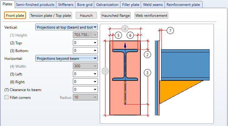
Plates
In this tab you can set the parameters for the following components:
To do so click on the respective button.
In this area you can determine the type, appearance and size of the plate on the girder (1st beam) as well as the direction of the plate in relation to the beam.
|
Semi-finished product |
By clicking on the |
||
|
The values for Vertical and Horizontal define the height and width of the plate as well as the projection. The following procedures are available: |
|||
|
Vertical |
|
||
|
Horizontal |
|
||
|
Clearance to beam |
If desired, enter a value for the clearance, i.e. the distance between the plate and the beam to be connected. |
||
|
Fillet corners |
You have the option to fillet the corners of the front plate by activating the checkbox and entering the fillet radius. |
||
The definition of the tension plate /top plate (at the column) essentially happens analogous to the definition of the front plate at the girder. Moreover, via Type of insertion you can decide whether the plate should be inserted (top plate), front-mounted /tension plate) or not be fitted.
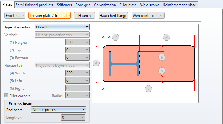
Via Process beam it can be determined how the column should be treated when inserting the plate.
- Do not process: The column will not be lengthened or shortened.
- Trim oblique: The column will be lengthened or shortened and - depending on the connected beam - trimmed oblique.
- Trim straight: The column will be lengthened or shortened.
When trimming the column the extension determines the projection of the column beyond the connected girder.
Here you define the parameters for the haunch. These are the length and height as well as the processing of the third corner. Under Type of insertion you determine whether the haunch should be inserted at the bottom, on top or not at all.
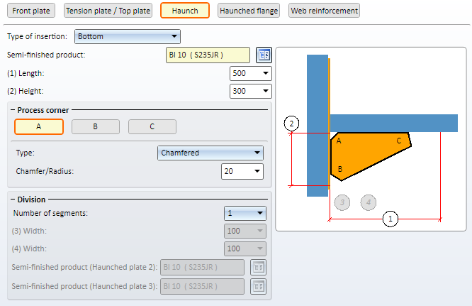
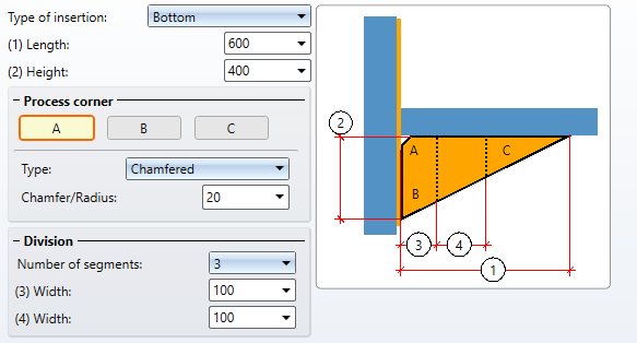
The haunch can also be divided into several (max. 3) segments, i.e. consist of three haunch plates. To do so, please enter the desired number of segments and select the desired semi-finished products.
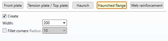
After clicking on the button Haunched flange you can select the width and the corner processing of the haunched flange. If no haunched flange shall be created deactivate the Create checkbox.
Here you can define the parameter for web reinforcement. Under Type of insertion you can select whether the web reinforcement should be fitted on the left, on the right, double-sided or not at all.

Semi-finished products
Here you can select the semi-finished products for the various sheets of the frame corner. To do this, click on the respective  symbol and select the semi-finished product in the catalogue.
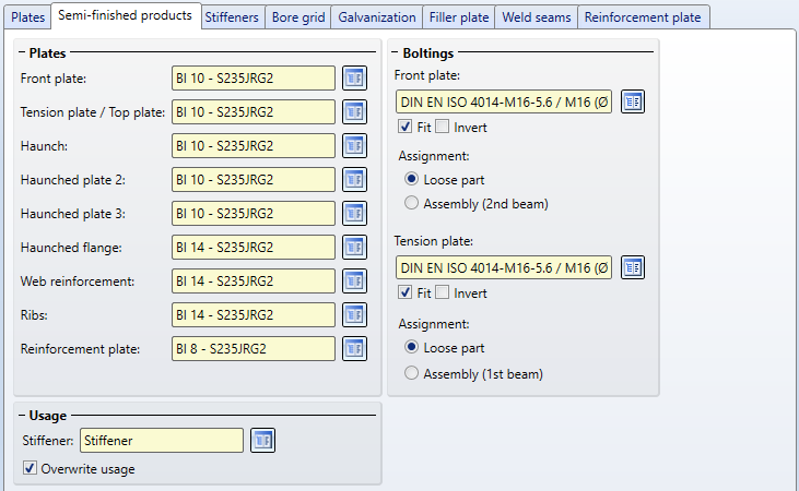
Under Bolting, you define the bolting of the front plates - separately for the Front plate and the Tension plate - e.g. the type of bolt, the bore diameter, etc. Click on the symbol and then compile the components of the bolted connection. To do this, click on the symbol and then put together the components of the bolted connection. The default setting is DIN EN ISO 4014-M16-5.6 / M16 (⌀ 17.5). The determination is carried out in the same way as for the Steel Engineering Bolting function.
The bolting will only be inserted if the Fit checkbox is active. If the bolting direction is to be inverted, activate the Invert checkbox.
For both the bolting on the front plate and on the tension plate, you can specify whether the bolting should be assigned to the Loose parts structure assembly or to the assembly of the second beam.
Stiffeners can be assigned a Usage at the bottom of the tab.
Stiffeners
The frame corner can either be inserted with stiffeners or without. Possible stiffeners are:
- three stiffeners at the column,
- a diagonal reinforcement stiffener at the column,
- a stiffener at the girder
- additional stiffeners at the column, as well as
- ribs at the girder.
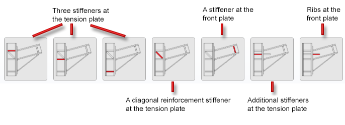
The settings can be modified separately for each stiffener. To do so click on the respective graphic and make the desired changes.
If a stiffener is to be inserted, firstly activate the Create checkbox and select the type of stiffener from the catalogue by clicking on the  symbol.
If the same settings should be applied to all three stiffeners at the column
click on All equal  .
.
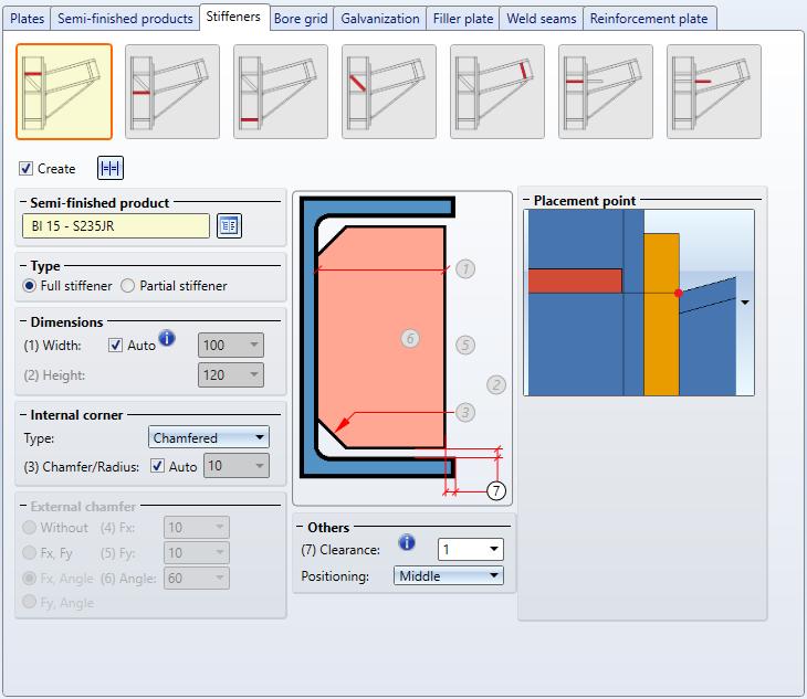
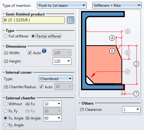
Further parameters for stiffeners:
|
Type |
By activating the respective radio button you can determine whether a full or partial stiffener will be inserted. |
||||||
|
Dimensions |
Full stiffener
(2) Clearance, (1) automatic width
Determine the height of the stiffener. |
||||||
|
Internal corner |
In this area you define the data for the internal corner. Depending on the selected corner options, these refer to the chamfer length or the fillet radius. If you want HiCAD to automatically determine the value, activate the Auto checkbox. |
||||||
|
External chamfer |
For partial stiffeners choose this option to regulate the external chamfer and then determine the values for the chamfer length or radius, depending on the selected option. |
||||||
|
Others |
Here you can enter a value for the clearance. The height of the full stiffener is rounded to whole millimetres. The clearance is adjusted in the process. For the stiffeners at the column you can moreover define the positioning and alignment of the stiffener. The stiffeners can be perpendicular or aligned - depending on the connected beam (girder). Under Positioning you can determine which edge should be relevant for the insertion - the front side, middle or back side. For stiffeners at the girder you can only select the positioning. They are always perpendicular.
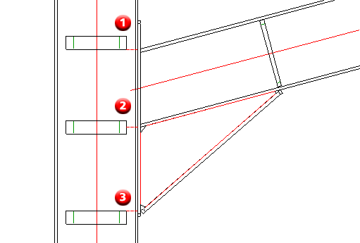
The upper stiffener has been aligned, the other two stiffeners are perpendicular. The following image shows the connection with three perpendicularly aligned stiffeners. For the first stiffener (1) the positioning Front side has been selected, for the middle stiffener (2) Middleand for stiffener (3) Back side.
An example: The image shows a frame corner with three stiffeners on the left. If a web reinforcement of thickness 50 / length 10000 / distance 400 is fitted, the depth of the middle and lower stiffener will be reduced by 50 and the stiffeners will be welded to the web reinforcement.
|
||||||
|
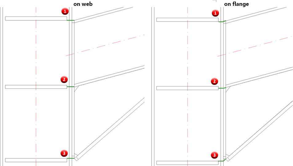
Placement point* |
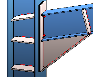
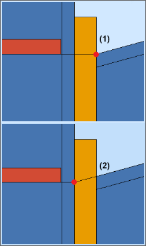
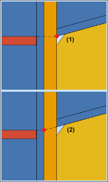
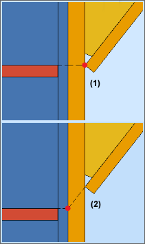
A placement point can be selected for each of the three stiffeners on the column. The stiffeners are then installed relative to the placement point. You can choose between the Web of the connecting profile (1) and the Flange of the connecting profile (2).
The image below shows a connection with three vertically aligned stiffeners. For the first stiffener (1) the Front side was chosen as placement, for the middle stiffener (2) the Middle and for the stiffener (3) the Back side. On the left, the Web of the connecting profile was chosen as the placement point, on the right, the Flange of the connecting profile.
|
 Auto
Auto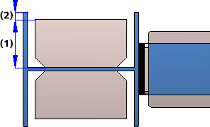


* only for the three stiffeners on the column
In order to insert additional stiffeners at the column click on the following symbol:

Subsequently, you can set the parameters for the additional stiffeners.
The stiffeners can either be installed perpendicular to the second beam or flush to the first beam. If no stiffeners should be installed, select the installation option Do not fit.
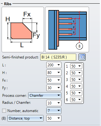
In the second selection box you can choose whether ribs should be installed at the girder as additional stiffeners. If you select Stiffeners + Ribs, you can determine the parameters for ribs after clicking on the

symbol.
Please note that the choice of installation for stiffeners and the installation of ribs is interdependent, i.e. selected options in the stiffeners' selection boxes will be applied to the ribs and vice versa. Example: You have selected the options Flush to 1st beam and Stiffeners + Ribs for the stiffeners. In the ribs parameters you select the Do not fit option, and it will be applied to the stiffeners, too.
A maximum of 7 ribs is possible. The automatic quantity determination refers to the boltings. Depending on the other parameters the ribs are always positioned in between two bolting rows.
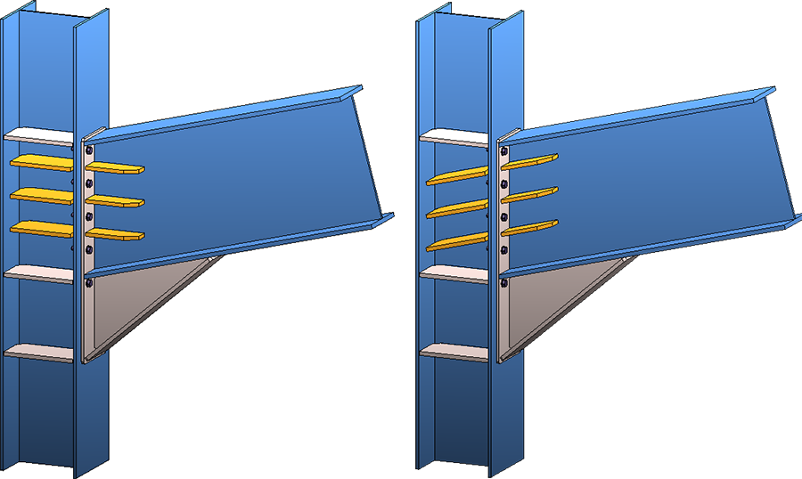
Automatic determination of rib quantity (here: 3) - left: perpendicular to 2nd beam, right: aligned to 1st beam
For the manual determination you enter the rib quantity and determine the distance between the first rib and the beam edge. This distance can refer to the upper or lower edge. Enter the distance between the first and the second rib under 1:; under 2: you enter the distance between the second and third rib and so forth.
In the following image five ribs have been installed without automatism.
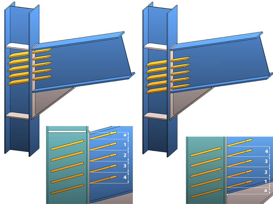
Left: a = distance to top, right: a = distance from below
Bore grid
The position of the bolting or the bore pattern on the end plates is determined by the bore grid. The settings can be made separately for the front plate and the tension plate.
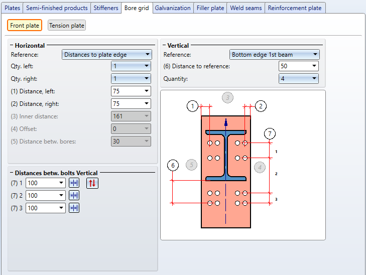
The reference must be selected first for both the horizontal and vertical settings. The other entries depend on the selected reference.
|
Reference Horizontal |
Entries |
|
Distance to plate edge |
|
|
Inner Distance
|
|
|
Distances to web |
|
|
Reference Vertical |
Entries |
|
Centred (Front plate) |
|
|
Top edge 1st beam |
|
|
Front plate, top |
|
|
Bottom edge 1st beam |
|
|
Front plate, bottom |
|
Vertically, you can use different distances between bores. If all bores should have the same distance in vertical you can also simplify the entry. Simply insert the distance value in the input field and click on the Equidistantsymbol. All fields will be filled with the entered value.
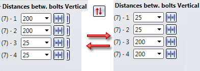
By clicking on the  symbol it is possible to flip the bore grid, and thus the boltings, vertically.
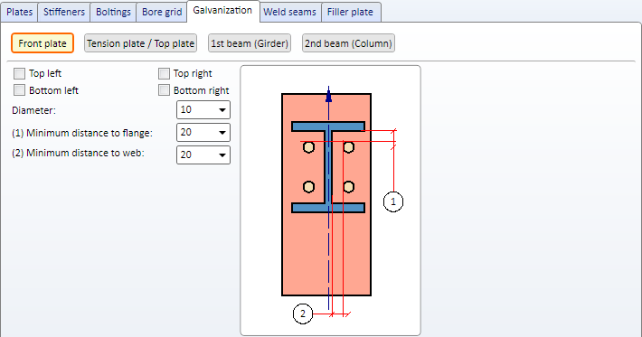
Galvanization
Here you can determine whether the front plates, tension plates / top plates and beams should be provided with galvanization holes. Click the respective button to do so.
1st / 2nd beam
Here you first of all select the desired processing. You can choose from the following:
- no processing
- Web cut
Choose whether the processing should be on top or on the bottom and enter the radius. - Holes
Choose whether the processing should be on top or on the bottom. Enter the hole diameter and the distance to the web (Distance X) and to the fillet on the beam (Distance Y).
Front plate, Tension plate/Top plate
Determine which holes should be created by activating the checkboxes and enter the hole diameter as well as the minimum distance to web and flange.
In the workshop drawings, only one of the zinc plating holes for galvanisation is annotated. Please note however that this principle only applies to zinc plating holes on beams.
Filler plate
If filler plates shall be inserted on the front plate between the front plate and the tension plate, you can determine the quantity, type and size in the Filler plate tab.
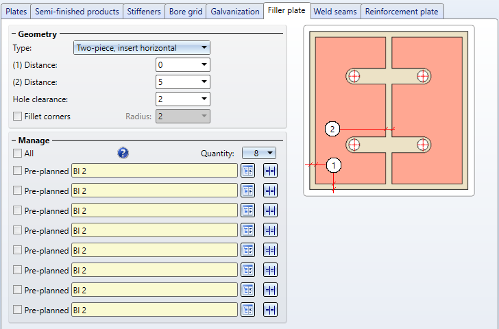
The following geometry types are available for filler plates:
- One-piece, insert left,
- One-piece, insert right,
- One-piece, insert at top,
- One-piece, insert at bottom,
- One-piece, drilled,
- Two-piece, insert horizontal and
- Two-piece, insert vertical.
Enter the required distances and the size of the hole clearance, depending on the selected geometry type. The hole clearance always refers to the bolt.
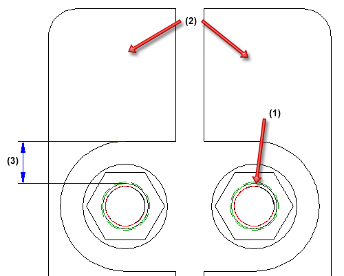
(1) Bolting diameter, (2) two-piece filler plate (3) hole clearance
Under Manage you can determine the quantity of filler plates.
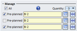
Select the desired plate type for each filler plate in the catalogue and determine whether the filler plate should be pre-planned or not by activating the checkbox. If the filler plate is pre-planned the beam will be shortened by the thickness of the filler plate. If they are not pre-planned they will be inserted next to the plate.
Via the symbol you have the option to apply the settings of one filler plate to all other filler plates.
By activating the All checkbox you can define all filler plates as pre-planned in one step.
Please note that filler plates that are not pre-planned will be displayed as transparent in the drawing, i.e. assigned to the layer 40.
Filler plates will not be assigned to the assembly of the beam but to the structure assembly Loose Parts. Moreover, filler plates are assigned the usage type Filler plate.
 If the bore grid is too narrow for filler plates to be inserted the plate will not be created. A feature log will be created nonetheless.
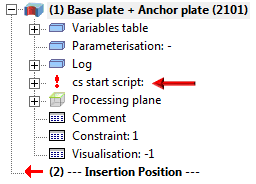
By double-clicking on the feature name you have the option to correct the settings.
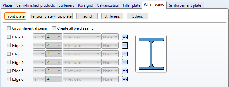
Weld seams
In this tab you determine which weld seams should be created. A distinction is made between weld seams
- on the front plate,
- on the tension plate / top plate ,
- on the stiffeners,
- on the haunch as well as
- on the reinforcement plates and web reinforcement (Others).
Click on the desired button in the tab on top and determine on which edges the weld seams should be produced by activating the respective checkboxes. The settings for stiffeners are always available.
For front plates you can choose whether
- a circumferential seam,
- weld seams on specific edged or
- all weld seams
should be created. For each edge you can select a type of thickness designation, a weld seam thickness, a weld seam type and an inspection category. If you want to use the same settings for the other edges, click the Equatesymbol.
For stiffeners, circumferential seams are often used in practice, which also makes drawing in particular much easier. You can achieve this by activating the corresponding checkbox.
Please also note that circumferential seams cannot be applied to haunches and ribs.
For continuous HV and HY weld seams, enter 0 as the weld seam thickness.
Reinforcement plate
Determine here whether the boltings on the front plate should be reinforced with plates.
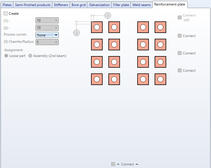
If reinforcement plates are to be inserted, activate the Create checkbox here.
Enter the distance between the bore and the edges of the reinforcement plate. If desired, select corner processing. The chamfers can be chamfered (45°) or filleted.
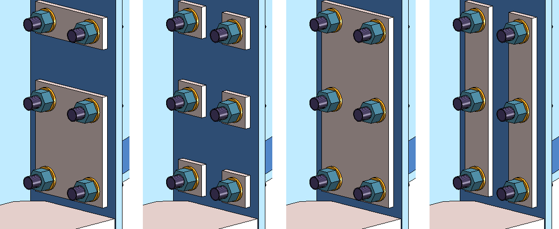
The number of reinforcement plates is determined by the Bore grid. The reinforcement plates can be connected both horizontally and vertically. The vertical connection can also be made row by row, e.g.
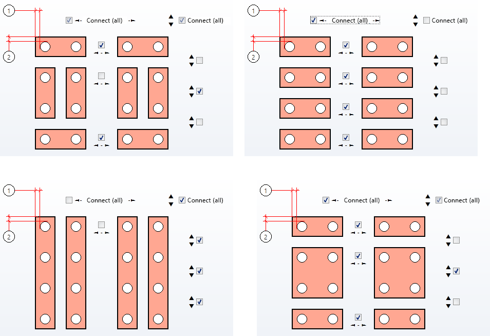
The following image shows some examples.
Reinforcement plates can be assigned either to the structure assembly Loose parts or to the assembly of the 2nd beam.

Connections + Variants (3-D SE) • Dialogue Window for Connections (3-D SE) • The Catalogue System for Connections + Variants (3-D SE) • Insert Connections - General Procedure (3-D SE)