Steel Engineering > New
There are various options available for the insertion of beams and profiles:
- You select the desired part in the catalogue. In addition to 3-D standard beams, these can also be multi-part standard beams, prototype beams or elongated plates.
- You use series that are created from 2-D contours or 2-D variants.
- You derive beams from a sketch.
- You use the cross-section of an existing beam in your drawing for a new beam.
- You use bar elements if you want to create a draft first.
All profiles can be installed as main parts or sub-parts.
|
Functions |
|||||||||||||||||
|---|---|---|---|---|---|---|---|---|---|---|---|---|---|---|---|---|---|
|
|
Insert new standard beam, prototype beam or elongated plate Insertion of 3-D standard beams, multi-part standard beams, prototype beams or elongated plates
Beneath Up to HiCAD 2022 you will find the functions available up to version HiCAD 2022 (V 2027.2) for inserting standard beams + profiles. These functions are also integrated in the Insert new beam |
||||||||||||||||
|
|
|
||||||||||||||||
|
|
Derives beams from sketches. Clicking
|
||||||||||||||||
|
|
New beam, take over cross-section from reference beam* Takes over the cross-section of an already existing beam |
||||||||||||||||
|
|
Inserts user-defined beams via factory standard catalogues. |
||||||||||||||||
|
|
Inserts user-defined beams by selecting them via the the Explorer. |
||||||||||||||||
|
|
Inserts user-defined beams via daocument master data. |
||||||||||||||||
|
|
Insert series, via DB article master* Inserts user-defined beams via article master data. |
||||||||||||||||
*The insertion function for sub-parts can be found in the pull-down menu  of the respective function.
Display of beam orientation
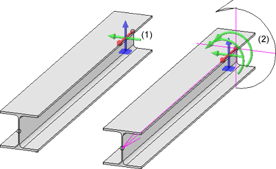
When inserting Steel Engineering beams and profiles, the orientation of the parts is displayed graphically as a coordinate system, i.e.
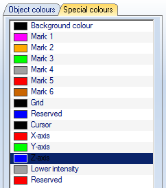
- axis direction (in the special colour X-axis),
- up/down (in the special colour Z-axis),
- left/right (in the special colour Y-axis),
- direction of rotation
at the start of the beam. The display occurs when the beam is visible and its position can still be changed.
When the beam orientation is to be displayed can be set in the Configuration Editor at System settings > Visualisation > Indicate orientation of active Steel Engineering beam.
- Only upon insertion
The orientation is only displayed when beams are installed. This is the default setting. - Always
The orientation is always displayed. - Switch on/off with F6 key
The orientation can be shown/hidden with the F6 key. Alternatively, you can use the button
 Show beam orientation or drawing orientation of the active 3-D part
on the Coordinate system toolbar (at the bottom of the HiCAD dialogue).
Please note that the size of the orientation symbol does not change when zooming.

(1) Display when activating, (2) Display during insertion
When the beam orientation is to be displayed can be set in the Configuration Editor at System settings > Visualisation > Indicate orientation of active Steel Engineering beam.
The colours of the orientation symbol can be changed with the Colour Editor at Drawing > Others.

When inserting catalogue standard parts and semi-finished products (Steel Engineering beams and plates) in HiCAD, the corresponding part attributes are partially assigned values from the catalogue entry. (e.g. the BZ column is transferred to the "Article number" part attribute). This assignment is freely configurable. For this purpose, it is possible to link a table column with a part attribute in the catalogue tables. If a part from this table is inserted in HiCAD, the value of the linked column is transferred to the part attribute. For example, a user can enter the article number and/or supplier in a column, whereby the value can be transferred to a part attribute during part insertion and used for part annotation or bill of materials. In the catalogue table (see Catalogue Editor), a link symbol is displayed in the column header for linked columns.In all HiCAD standard tables for standard parts+semi-finished products, the column "BZ" is linked with the part attribute "$BB", the column "CUSTOM1" with the part attribute "CUSTOM1" and the column "CUSTOM2" with the part attribute "CUSTOM2".
Please also read the notes on automatic dimension calculation.

Insertion Options for Beams and Profiles (3-D SE) • Steel Engineering Functions • General Information (3-D SE)


