Multi-Part Beam, From Sketch
Steel Engineering > New > Standard  > Multi-part beam from sketch
Use this function to derive a multi-part beam from sketches in the current drawing.
 Important:
- Each element consisting of connected lines must be one, individual sketch.
- If there are several sketches, they need to be subordinated to one 3-D dummy part.
- Sketches with ramifications must also be subordinated to one 3-D dummy part
Proceed as follows:
- Create the corresponding sketches if required. When drawing the sketches, note that the distance to the coordinate system is crucial for the subsequent position of the fitted beam. The beam is fitted at a distance from the XY-plane that is identical to the distance of the sketch to the origin of the coordinate system. The beam axis is always placed in the coordinate origin.
- If the sketch has ramifications or if several sketches are to be used, create a superordinate 3-D dummy part for the sketch. In the ICN, drag the sketch below this dummy part.
- Select the Multi-part beam from sketch function.
- Identify the dummy part containing the sketches (preferably in the ICN, as this is the fastest method).
- Specify whether the sketch is to be deleted after the creation of the beam.
- Specify the start point of the beam axis.
- The actual insertion dialogue will then be displayed, which is similar to that for the insertion of standard beams. Choose the desired insertion options, specify the start point and, if applicable, the end point of the beam.
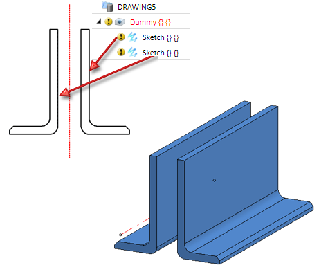
Multi-part beam, derived from a dummy part with two sketches (left)


Insertion Options for Beams and Profiles (3-D SE) • Insert Beams (3-D SE) • Steel Engineering Functions