Drawing > Itemisation/Detailing > Orient...
With the functions found at Drawing > Itemisation/Detailing > Orient... you have the possibility to determine for assemblies, general 3-D parts, beams and profiles, sheets and plates as well as pipelines in Plant Engineering which plane of the active view is to be considered as front view or top view when deriving the drawing. Furthermore, the orientation is also taken into account when calculating assembly dimensions.
If the HiCAD dimension calculation is active, then you also have the option of changing the dimension orientation. This can be useful, for example, to determine optimal product packaging or to optimise the transport of equipment etc.
|
Part orientation |
|
|
|
|
|
|
|
|
|
|
|
Dimension orientation |
|
|
|
|
|
|
Orientation of the dimension by selecting the top side |
|
|
Reset dimension orientation (for manually set orientations) |


Example:
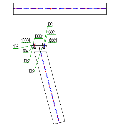
Let us assume that you want to create a workshop drawing for the model drawing shown below.
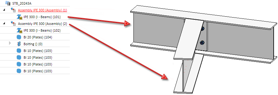
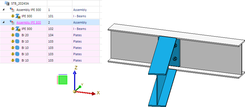
For the second assembly (beam, plate and bolting), select the Define front view for derived drawings function and then choose the screen plane. This is highlighted accordingly in the drawing.
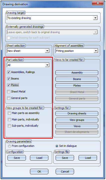
Now, create the workshop drawing:
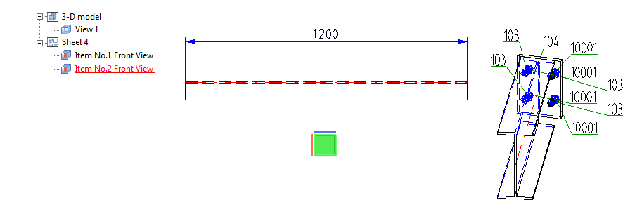
In this example, the Front view has been chosen everywhere.
In the workshop drawing, the view selected with the Front view function is taken into account for Assembly 2. This is also highlighted accordingly here.
If you now select Reset, the workshop drawing will look as follows:


Derive Drawing • Drawing Derivation • Drawing Derivation: Dialogue Window • Usage-Dependent Configurations