3-D Standard > Standard Processings > Bore  > Processing direction
This function indicates the processing direction and processing side of a part, e.g. a sheet metal flange, in order to define the grain or coating direction. For this purpose, the following symbols for the direction arrows are available in the Werksnormen/Symbole/Pfeile catalogue:
|
|
Direction symbol |
|
|
Direction symbol, Composite panel |
|
|
Direction symbol, one-sided |


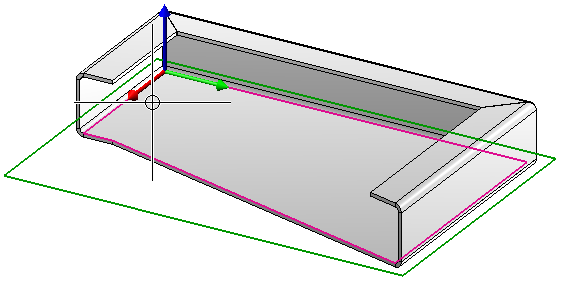
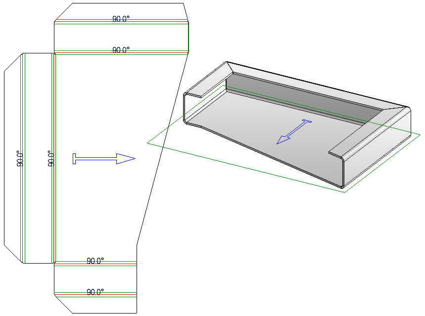
When creating developments of Sheet Metal parts, the direction can optionally be used to align the development. This creates the development from the side on which the arrow is located and automatically aligns it horizontally to the direction symbol.
Proceed as follows:
- First select the sheet flange you ant to process.
This processing cannot be applied to Sheet Metal main parts.
- Call the Processing direction function. The Settings dialogue window will be displayed (if you have not activated the Suppress window option beforehand.
- Specify the required settings and confirm with OK.
- Identify the surface to be processed, e.g. via 2 edges or 2 points.
- Select an arrow size.
- Specify the insertion position.
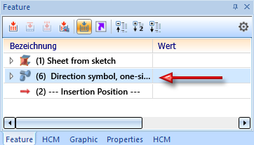
To remove a direction symbol, delete the corresponding entry in the feature log.
The processing direction is also taken into account when calculating dimensions and aligning parts.
![]() Please note:
Please note:
- If you activate the Sheet Alignment: Automatic option for a development instead of the sheet metal part, the side with the direction symbol will be optionally developed.
-
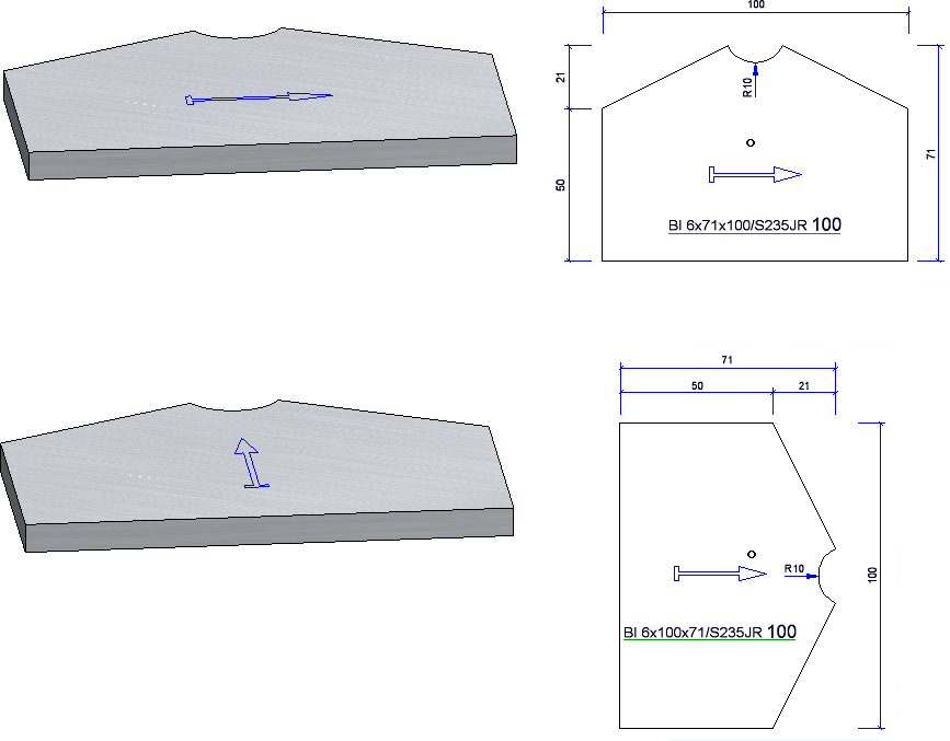
When calculating the length and width of Steel Engineering plates and Sheet Metal parts, the processing direction is taken into account.
Example:
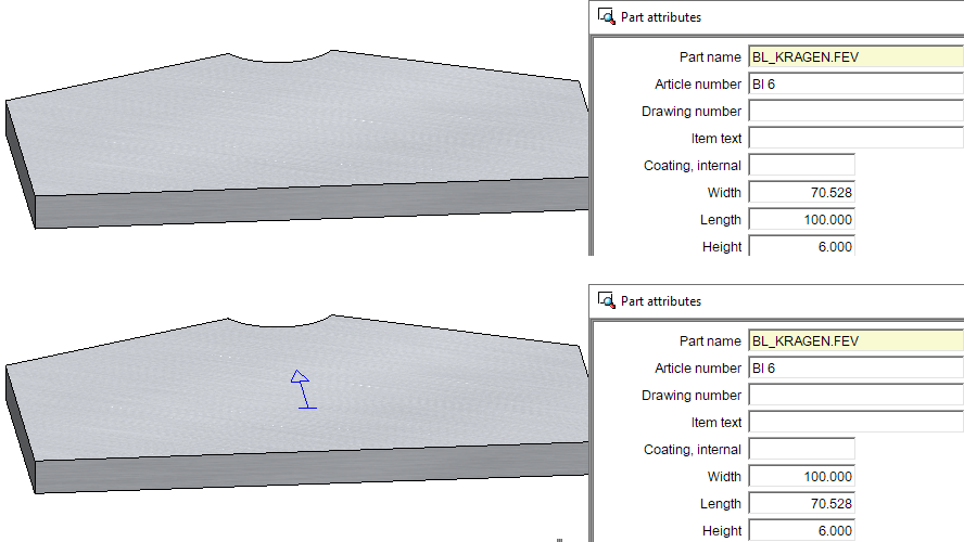
This also affects the position of the plate in the workshop drawing.