Insert Point Clouds
 > Point cloud
Point cloud > Point cloud > PtCloud
Point clouds can only be inserted into an existing model drawing, i.e. before importing, you must either create a new HiCAD drawing or load an existing model drawing.
To import a point cloud (format .lsproj) to HiCAD, select the Insert point cloud function - either directly on the Point cloud tab or from the Drawing > Insert Part > Exp. > ... menu.
Then select the desired file. If you have previously converted the point cloud with the HiCAD Point Cloud Converter, note that the converted file is stored by default in the path specified in the FILEGRUP.DAT file under N:. The default setting is the sub-folder punktwolken of the HiCAD installation.
The file will be inserted into the existing drawing.
To align the point cloud in the construction, HiCAD now requests the determination of two point cloud points after importing a point cloud. These are always located on the visible part of the scanned object. These points, together with the Z-direction of the point cloud, define the part coordinate system. To determine the point cloud points, HiCAD automatically activates the point option (PW) Point from point cloud.
- Specify the first point cloud point. This defines the origin of the Part CS.
- The second point cloud point determines the X direction of the Part CS.
The determination of the two points and the installation direction are graphically visualized in the model drawing. Point cloud points are represented by a red point.
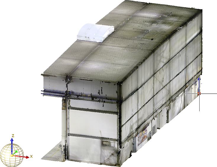
Determining of first point (Image: VHV Anlagenbau GmbH, Hörstel)
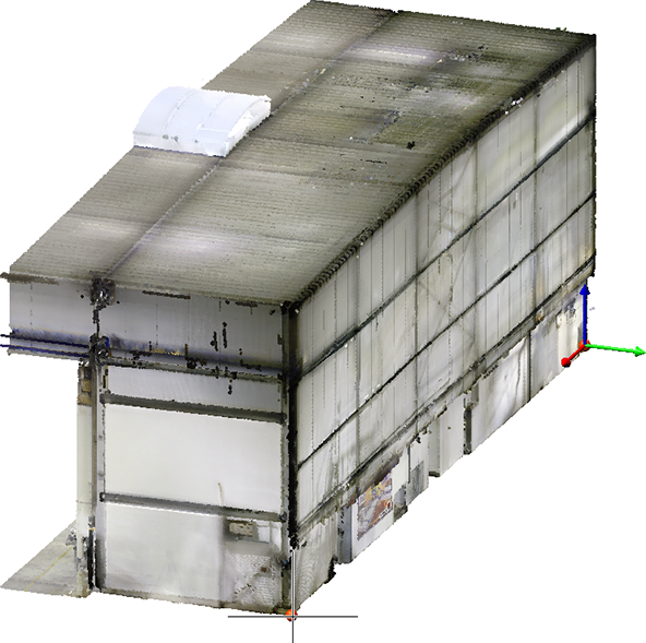
Determining of second point and visualisation of fitting direction (Image: VHV Anlagenbau GmbH, Hörstel)
After determining the points, the point cloud is rotated so that the Part CS coincides with the World CS.
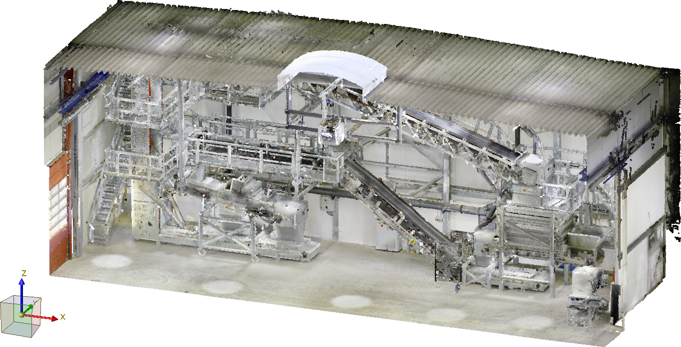
Example of a point cloud imported to HiCAD (Image: VHV Anlagenbau GmbH, Hörstel)
Point clouds are usually very large. To see the entire contents of the point cloud, you may need to call the View all function after the import.
The point cloud has the geometry type Dummy in HiCAD and is marked with the  symbol in the 3-D part structure of the ICN. The name of the imported file is used as part name, for example:
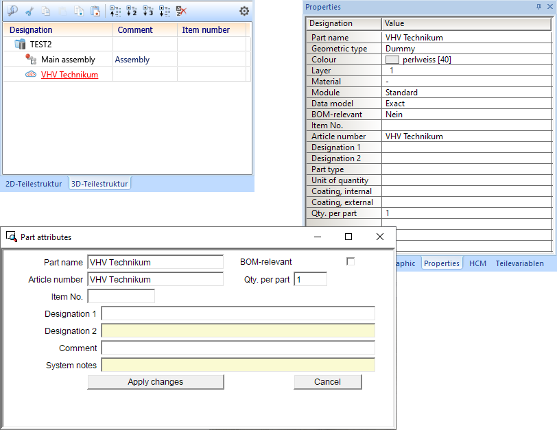
As with other parts, the part attributes of a point cloud can be defined.
It may be necessary to align the point cloud with the world coordinate system for better orientation - especially if the corresponding CAD model is to be created based on the point cloud. To do this, the point cloud can be rotated and moved as required using the Transform functions of HiCAD.
The 3-D point option (PW) Point from point cloud allows you to select specific points in a point cloud. These points always lie on the visible part of the scanned objects. This function is particularly important if you want to measure parts of the point cloud.
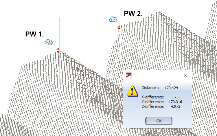
Distance between 2 point cloud points
For the processing and measurement of point clouds
- the clipping function on the Point cloud tab
- the functions of the context menu for point clouds
- the measurement functions of the Information tab
- the zoom functions
etc. can be used. Most view functions can also be applied to point clouds. Furthermore, point clouds can be copied and also referenced.
Please note that using the function Views > Edit > Clip... function is not recommended here.
To dynamically cut point clouds, use the clipping functions on the Point cloud tab.
![]() Please note:
Please note:
If a representation type that cannot display point clouds is selected when installing a point cloud, the representation type of the active view is automatically set to Shaded with edges.

