Drawing > Itemisation/Detailing > Drawing derivation 
The settings required for derived drawings can either
- be set in the dialogue, or
- loaded from the configuration.
Set drawing parameters in the dialogue
If you select this option, you set the drawing parameters manually by activating the corresponding checkboxes and radio buttons and selection of entries from list boxes.
You can save these settings and re-use them later, if required. To do this, click the Save button in the Settings file area. Enter the name and the path of the file. By default, the HiCAD SYS directory will be suggested. The pre-settings defined by the ISD are stored in the file WSD_DLG_GENERATE.DAT.
Load drawing parameters from configuration
Besides the above described option you can also use configurations which are managed via the Configuration Editor. These configurations are assigned to the Usage part attribute and offer, in addition to the options provided by the dialogue window, further possibilities for the creation of individual, customer-specific workshop drawings. They enable the creation of workshop drawings for a particular usage, e.g. for girders, columns, mullions, transoms etc., or define individual dimensioning rules for each dimension of the workshop drawing. Please note that such configurations should only be created and provided to you by an administrator. The ISD has predefined various, usage-dependent configurations (BEAM= horizontal beam, girder; COLUMN=vertical beam, column), as well as default configurations for certain part types (e.g. I-beams, plates, steel pipes etc.):
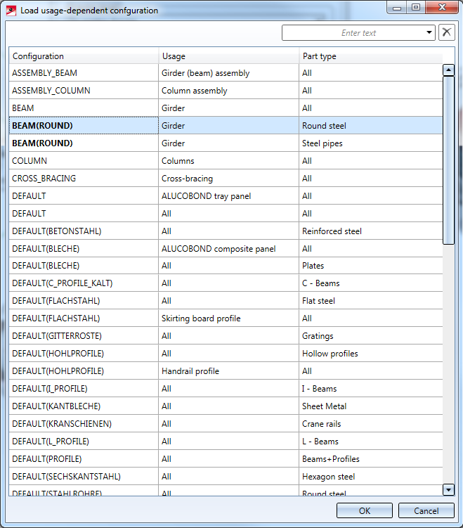
- On the left gap are the names of the available Configuration templates from the Configuration management (in Configuration management under Automatic drawing derivation > Production drawing > Usage-dependent).
-
The middle column shows the usage type from which the configuration template is used.
- The right gap shows for which usage type the Configuration template is used.
The sorting of the displayed list can be changed by clicking on the column header.
The selection can be filtered using the search field at the top right of the dialogue window. Filtering can be cancelled by clicking on the delete icon.
Select the desired configuration and exit the window with OK.
After loading of a configuration you have the option to change the global settings of the dialogue window and save the configuration with these settings. The creation of new settings is not possible here.
Please also read the information given in the Usage-Dependent Configurations topic.
 Please note:
- For derived drawings, the dimensioning of parts and assemblies normally takes place according to the dimensioning rules specified in the Configuration Editor (isdconfigeditor.exe) for different usages. These settings apply even if the Drawing parameters: Set in dialogue option has been activated in the dialogue window for drawing derivations.
If you do not want to use any dimensioning rules you need to change the usage configurations accordingly. In the Configuration Editor, go to ..> Automatic drawing derivation > Production drawing > Usage-dependent > NAME > Views, with NAME being the name of the corresponding usage, i.e. dimensions will be created according to the for example RAILING. Use the Create dimensioning parameter to choose whether
- dimensioning rules are to be used,
- no dimensions are to be created at all, or
- conventional dimensioning is to be used, i.e. the dimensioning takes place according to the settings specified with the Dimensioning Settings function.
- The DIN frames, too, are loaded from the configuration. If no configuration file is available, or if such file cannot be read properly, or if no blocks with correct entries for drawing frames are available below the name area "DRAWING_FRAMES", no drawing frames will be created in the workshop drawing, or existing frames will be deleted when an updating is performed.
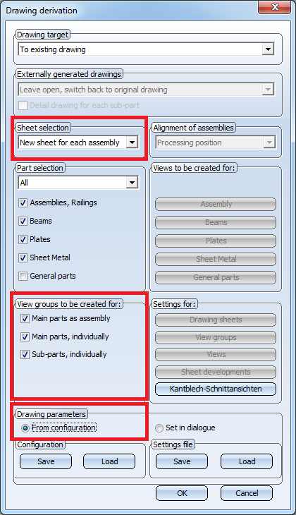
- When generating production drawings with the options
- Sheet selection:
New sheet for each assembly, - Drawing parameters:
 From configuration,
 - View groups to be created for:
 Main parts as assembly Main parts, individually Sub-parts, individually,
the drawing frames assigned to each assembly will be used. Up until now this has only been the case if only the assembly (main parts as assembly) has been detailed in the drawing.
An example:
The drawing contains the following parts:
|
Object |
Usage-dependent settings |
Assigned drawing frame |
|---|---|---|
|
Assembly with the usage: Girder (beam) assembly |
ASSEMBLY_BEAM |
DIN_A2 |
|
I-Beam (main part) |
DFEAULT(I_PROFILE) |
DIN_A4H_BLECHE |
|
Plate (sub-part) |
DEFAULT(Bleche) |
DIN_A4H_PROFILE |
If the production drawing is now be created as follows,
the drawing frame of the production drawing will be DIN_A2.
- If you use an external drawing as drawing target, and load the drawing parameters from a predefined configuration, parts appearing exclusively as "attached parts" in the workshop drawing will also be included in the drawing BOMs. You can change this behaviour in the Configuration Editor (ISDConfigEditor.exe) if desired: Select ... > Automatic drawing derivation > Production drawing > , and set the parameter Remove BOM-relevance of non-detailed parts in external drawing to 1 (yes). The parts will then no longer be BOM-relevant.


Derive Drawing • Drawing Derivation • Drawing Derivation: Dialogue Window • Usage-Dependent Configurations