Dimensioning Settings
Drawing > Itemisation/Detailing > Dim.  > Dimensioning Settings
For Drawing derivations, the dimensioning of parts and assemblies normally takes place according to the dimensioning rules specified in the Configuration Editor (isdconfigeditor.exe) for the different usages. These settings apply even if the Drawing parameters: Set in dialogue option has been activated in the dialogue window for drawing derivations.
If you do not want to use this dimensioning rule but the conventional dimensioning rule, you need to change the Usage configurations accordingly.
In the Configuration Editor, select ..> Automatic drawing derivation > Production drawing > Usage-dependent > NAME > Views, with NAME being the name of the corresponding usage, i.e. for example ASSEMBLY_BEAM, and set the Create dimensioning parameter to Conventional.
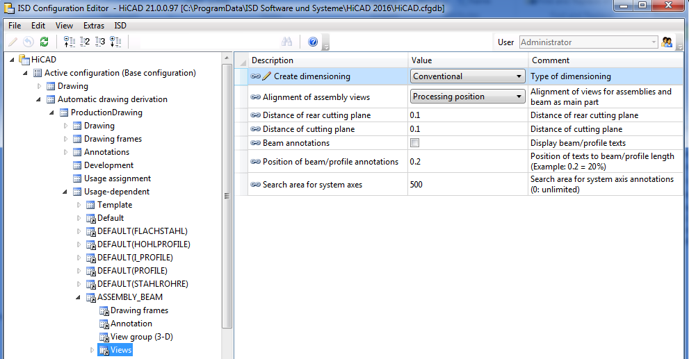
If the parameter is set to Conventional, not the settings in the Configuration Editor, but the conventional dimensioning settings from the STW_DimSettings.xml file in the HiCAD sys directory will be used.
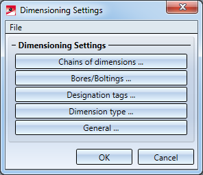
This concerns:
- Chains of dimensions
- Bores / Boltings
- Designation tags
- the Dimension type, and
- General settings for the dimensioning.
When you call the function the Dimensioning Settings window is displayed. Select which settings window you want to activate by clicking the appropriate button.
![]()
- The settings included in the STW_DIMSETTINGS.XML file can be modified in the displayed dialogue window. The parameters are automatically applied after changing the settings. For a permanent storage select the File > Save as function.
- The settings for chains of dimensions only apply to conventional dimensioning, whilst the other settings can also partly influence the dimensioning rules.
- For sectional views, it can be defined whether the dimensioning of 90° bend angle for sectional views of sheet metal can be defined in drawing derivation. The ISD default settings are that all bend angle are to be dimensioned.
In order to deactivate the dimensioning of 90° bend angle, currently the system files
- STAB3DPAR.DAT (new customers) or
- STW_DIMSETTINGS.XML
must be adjusted manually.
STAB3DPAR.DAT
Here, the setting is done via
Display right angle for opening angle of bend zones of sheet metal? 1:yes, 0:no
0
STW_DIMSETTINGS.XML
Here, deactivating the dimensioning is done via line
</PARAM><PARAM Name="SHOWRIGHTANGLEOFBENDZONE" Typ="INT" Value="0">
If this line is not available it must be added manually.

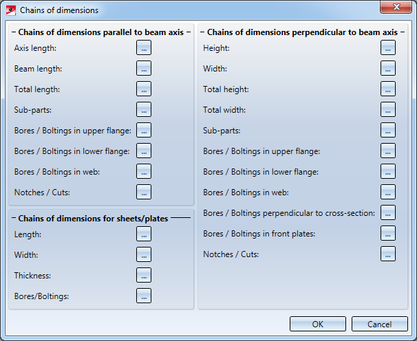
Chains of dimensions
The Chains of dimensions window enables you to individually specify for:
- chains of dimensions parallel to the beam axis,
- chains of dimensions perpendicular to then beam axis, and
- chains of dimensions for sheets and plates,
to which views you want to apply the dimensionings. Click the Select views... button to the right of the appropriate entry and select the desired views by activating or deactivating the corresponding checkboxes.
When you exit the window with OK, the Settings for dimensioning window is displayed again.
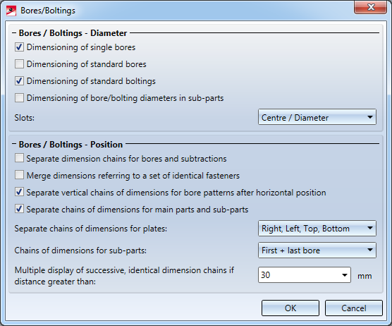
Bores/Boltings
In this dialogue window you specify which bore and bolting diameters you want to dimension, and the way in which you want to dimension slots: Do not dimension, Length/Width or Centre/Diameter.
In addition, you can influence the position of dimensionings for bores/boltings. You can, for instance, specify whether you want to separate chains of dimensions for main parts and sub-parts, etc. Moreover, you can determine that separate chains of dimensions for bores (through holes and standard bores) and subtractions should be created.
When you exit the window with OK, the Settings for dimensioning window is displayed again.
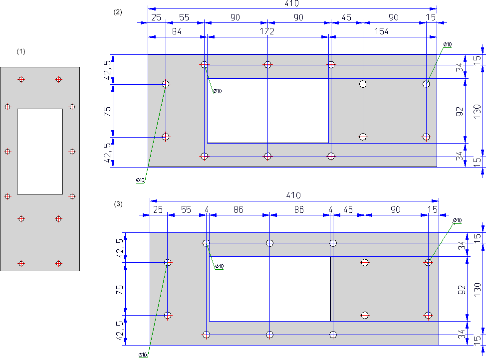
Example - Separate chains of dimensions for bores and subtractions
The depicted drawing (1) contains several through holes bores and one rectangular subtraction. (2) separate chains of dimension, (3) one chain of dimensions for bores and subtractions
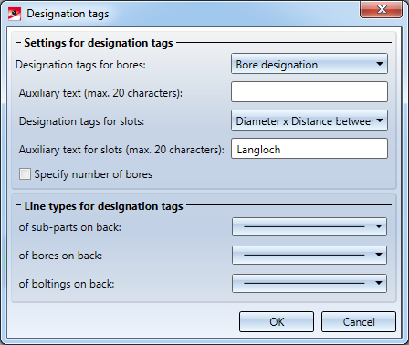
Designation tags
This function enables you to define various settings for the designation tags in a workshop drawing.
For example, you can select for bore designation tags whether you want to use the designation for the bore or for the appropriate bolt. Furthermore, you can add an auxiliary text consisting of up to 20 characters and you can determine whether the number of bores is specified or not.
If the Specify number of bores checkbox is activated, bores which are the same but do not belong to the same bore pattern will be combined.
However, this will only apply under the following conditions:
- The bores belong to one part.
- The bores lie on the same side of the main part.
- The bores have the same diameter.
- It is a single bore and not a bore pattern and
- ALL bores of the part meet these conditions.
In the lower part of the dialogue window you can select a different line type for the designation tag for sub-parts, bores or boltings on the back of a part.
The checkbox next to the respective selection box determines whether the designation tabs of sub-parts, bores and boltings on the back of the part will be either displayed or not. The checkbox is activated by default, i.e. the designation tabs will be displayed.
Deactivating the bores checkbox makes sense e.g. in the hidden line mode, as the bores are not visible in this case, hence it does not make sense to label them. This setting affects not only conventional dimensioning but also the dimensioning rules.
When you exit the window with OK, the Settings for dimensioning window is displayed again.
Additional text for slots
The content of the text key @PMU3941 from HiCAD text service (as displayed in the editor TEXTTABLESEDITOR.EXE) is predefined by ISD. In this case, the text is Slot. This allocation is being determined in the file stw_dimsettings.xml (in HiCAD sys-directory) by the row
</PARAM><PARAM Name="SLOTTEDHOLEADDTEXT" Typ="STRING" Value="%TS(@PMU3941)">
The preallocation is as multilingual and thus advantageous.
If you replace this text in the input field, it becomes subject to the new preallocation for the active HiCAD session. When restarting HiCAD, the file stw_dimsettings.xml is being used as predefined setting again.
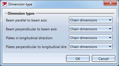
Dimension type
Use this function to specify the type of dimensioning in the workshop drawing. Possible are:
- Chain dimension
- Running dimension
- Coordinate dimension
- Running chain dimension
The selection can be separately applied to
- Beams parallel to beam axis
- Beams perpendicular to beam axis
- Plates in longitudinal direction and
- Plates perpendicular to longitudinal direction.
When you exit the window with OK, the Settings for dimensioning window is displayed again.
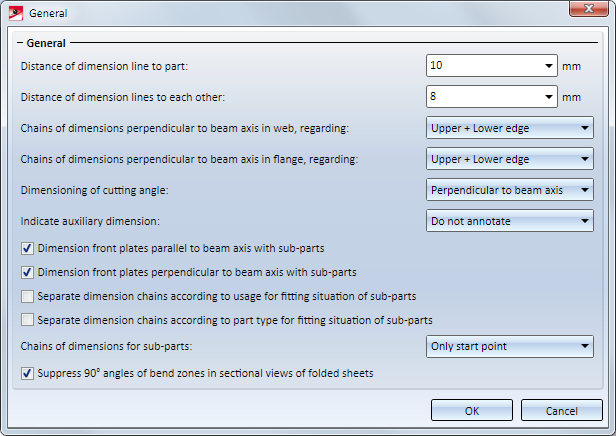
General
Use this function to define general settings.
Examples are:
- distance of the dimension line to the part
- distances between the dimension lines
- chains of dimensions perpendicular to beam axes regarding lower edge, upper edge, lower+upper edge or axis
- dimensioning of front plates
- etc.
Furthermore you can determine
- whether separated chains should be produced depending on type of usage for chains of dimensions which describe the fitting situation of parts, or not (by default yes). In the STW_DIMSETTINGS:XML file the corresponding line is </PARAM><PARAM Name="SEPARATEDSUBPARTPOSITION" Typ="INT" Value="1"> (1=separated, 0=do not separated).
- whether both contact points or only the first contact point of the chain should be dimensioned when dimensioning attached plates and plates and beams, which border on relevant beams (by default only the starting point). In the STW_DIMSETTINGS:XML file the corresponding line is </PARAM><PARAM Name="SUBPARTPOSITION" Typ="INT" Value="1"> (1=only starting point, 0=starting and end point).
- whether the attached parts (beams) should be dimensioned depending on the Part type attribute in the different chains of dimensions. In this way it is possible to dimension hollow profiles / attached parts separately from round steel / attached part, thus improving the dimension structure.
- whether the 90° bend angle should be dimensioned for drawing derivation in the sectional view of folded sheets. The ISD default settings are that all bend angle are not to be dimensioned. This applies to the file STW_DIMSETTINGS.XML and its column </PARAM><PARAM Name="SHOWRIGHTANGLEOFBENDZONE" Typ="INT" Value="0">.
- whether hidden parts and processings should be ignored. The setting predefined by ISD is no. This corresponds in the file STW_DIMSETTINGS.XML to the line </PARAM><PARAM Name="IGNOREHIDDENSUBPARTANDBORES" Typ="INT" Value="0"> or in the file STAB3DPAR.DAT (new customers) to the entry ignore base points on invisible parts and bores? 1:yes, 0:no
When you exit the window with OK, the Dimensioning Settings window is displayed again.
Please note that any settings performed are only the default settings for subsequent function call during the current HiCAD session. After restarting, the settings predefined by HiCAD are active. If you require your settings permanently, you have to adjust the file STW_DIMSETTINGS.XML or STAB3DPAR.DAT (new customers) accordingly in the sys-directory.

Drawing Derivation • Derived Drawings: Settings • Drawing Derivation: Dialogue Window