HiCAD supports a part classification according to freely definable usages. You can, for example, define parts as columns, girders, mullions, transoms etc. This classification takes place by selecting the Part attributes function and assigning the Usage attribute to the part. This will enable you to create Usage-dependent workshop drawings, i.e. you can, for instance, individually specify dimensioning rules for the different usages.
The configuration takes place in the Configuration Editor, the definition of new usages in the Catalogue Editor.
Settings in the Configuration Editor
- General settings
- Drawing
- Drawing frames
- Annotations
- Development
- Usage assignment
- Usage
- Part Type
- Usage-dependent settings
- Buttons
- Usage-dependent
- Usage-dependent drawing frames
- Dimensioning rules

Settings in the Configuration Editor
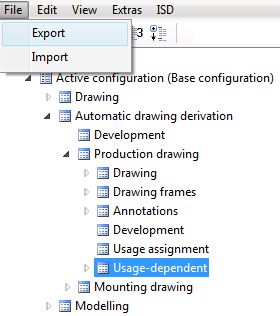
All settings that are relevant for the generation of detail drawings and workshop drawings are specified in the Configuration Editor and saved to the configuration database HICAD.cfgdb in the CONFIGURATION directory of your HiCAD installation. This database (or parts of it) can be imported and exported. The settings for detail drawings and workshop drawings can be found at Automatic drawing derivation.
For instance, if you want to import only the Usage area, mark it and select File > Import.
Please note that the selected parameter configuration template affects the settings for drawing derivation. This applies in particular for Steel/Metal Engineering.
General settings
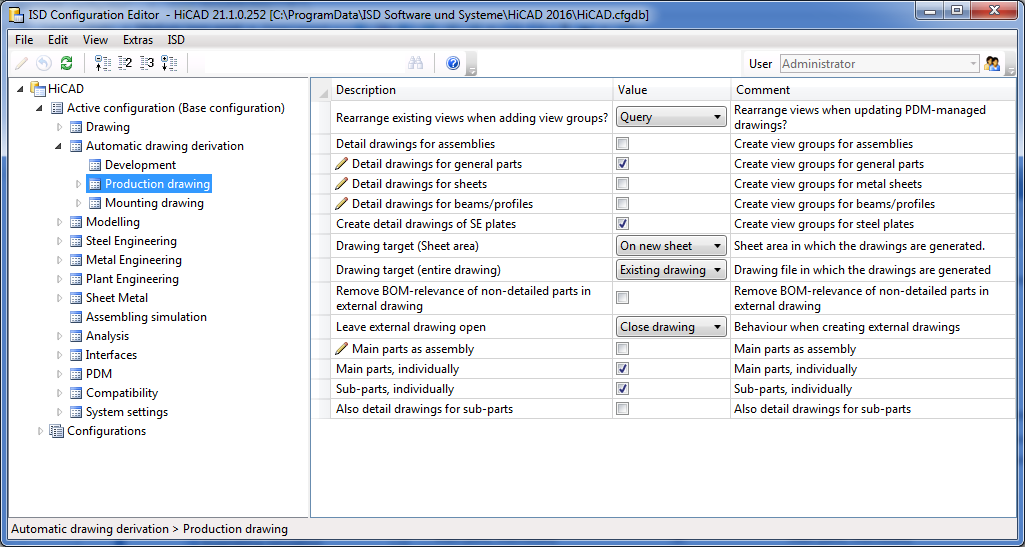
At Automatic drawing derivation you can specify general settings for the generation of detail drawings and workshop drawings. Basically, these are the presettings for the Derived drawing dialogue window.
Moreover, by activating the Avoid multiple sectional views checkbox you determine that sectional views with the same content will only be created once in the workshop drawing. Sectional views are considered equal if
- the parts visible (displayed) in the sectional views have the same valid item number and
- the sectional views contain the same geometries.
Sectional views for plates outside of the plate end (front plates, top plates, base plates mean the same) are generally unequal.
 If you have chosen the Steel/Metal Engineering template in the HiCAD Parameter configuration dialogue window (double-click ParKonfigComp.exe in the exe directory of your HiCAD installation to open this window), the Avoid multiple sectional views checkbox will be active by default.
Drawing
At Automatic drawing derivation > Production drawing > Drawing you will find pre-settings options for the Settings for Drawing Sheets dialogue window.
Drawing frames
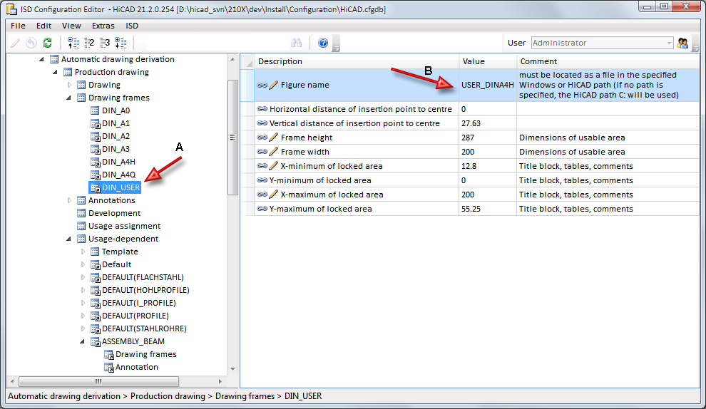
Here you will find all drawing frames that can be selected for the derived drawing and various setting options for them. Please note that you can also specify HiCAD or Windows paths here, namely, via the Figure name parameter. In the Value field, you can precede the figure name by a path.
Examples:
- DINA4
DINA4.FIG file from the HiCAD file group C: (this is the path entered for C: in the Filegrup.dat system file) - X:DINA4
DINA4.FIG file from the HiCAD file group X (this is the path entered for X: in the Filegrup.dat system file) - C:\TEST\DINA4
DINA4.FIG file in the Windows directory C:\TEST
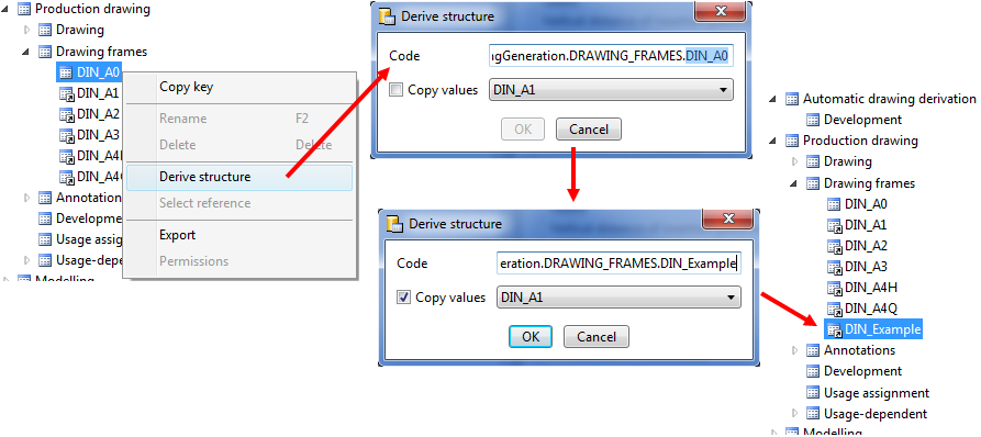
If you want to add further drawing frames for workshop drawings, proceed as follows:
Create the 2-D geometry of the new drawing frame. This can be easiest achieved by copying an existing drawing frame and changing the copy (e.g. DIN_Example) of this drawing frame.
Start the Configuration Editor and right-click the DIN_A0 drawing frame.
Select Derive structure.
In the Code field, replace the string DIN_A0 with the name of the new drawing frame, e.g. DIN-Example. If you want to copy the settings of other drawing frame for this new frame, activate the Copy values checkbox.
Then, adjust the settings for the new frame as required, notably the Figure name field.
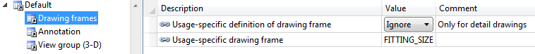
For the output of detail drawings you can also specify usage-dependent drawing frames. At Usage-dependent you can define a usage for the corresponding area of the drawing frame.
For the parameter Usage-specific drawing frame you need to enter the name A specified beneath Drawing frames in the structure tree, and not the name of the figure file B!
Annotations
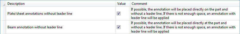
Placing of annotations
The annotations of beams and sheets in workshop drawings can be made with or without leader lines. This can be adjusted under Placing of annotations. The checkboxes are activated by default. This means that the annotations are placed direction on the sheet or beam. If there is not enough space to do so, the annotations will be done with leader lines.
If the checkboxes are deactivated, the annotations are categorically produced with leader lines.
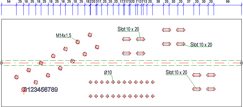
If the checkbox is active, the annotations of standard processings are located directly aside the processing - i.e. on the part - if there is enough space. If there is not enough space, the annotation is placed further away.
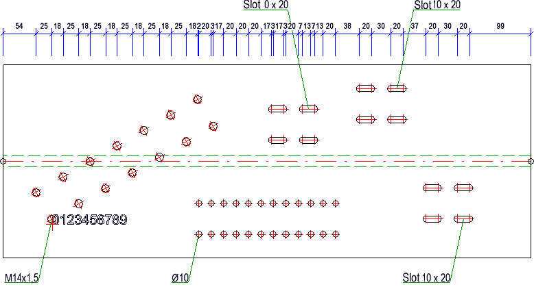
If the checkbox is inactive, the annotations are - as before - placed outside the part. The leader lines now always go to the nearest standard processing.
An example:
- Standard Processing on part: yes
- Standard Processing on part: no
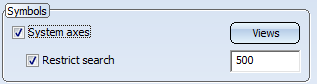
Grid annotations
The settings for Grid annotation determine the representation of system axes in the workshop drawing. This means that if in the Settings for views dialogue window the System axes checkbox has been activated, these settings will be taken into account.
Development
These settings refer to sheet metal developments in workshop drawings. For example, you can set the scale here and determine whether angular dimensions should be created in sectional views.
Usage assignment
HiCAD supports a part classification according to freely definable usages. You can, for example, define parts as columns, girders, mullions, transoms etc. This classification takes place by selecting the Part attributes function and assigning the Usage attribute to the part. For many functions, this happens automatically, e.g. for railing configurations. For a manual assigning of a Usage, you use the Part attributes in the context menu for 3-D parts.
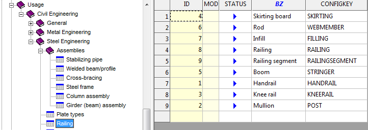
The valid usages are defined in the Factory standards catalogue. To each Usage a configuration key (CONFIGKEY) is assigned there.
For the creation of usage-dependent workshop drawings you can assign to each usage a usage-dependent configuration in which the parameters for the drawing derivation are specified. If desired, the assignment can also be limited to particular part types. The usage is assigned at ..> Automatic drawing derivation > Production drawing > Usage assignment (Key name: WSD_USAGEMAP).
For example, the configuration RAILING is assigned to the usage Railing there, the configuration STRINGER is assigned to the usage Handrail etc. The configurations themselves can be found at Automatic drawing derivation > Production drawing > Usage-dependent, e.g. the configuration RAILING.
The usages can be neatly arranged into groups. Predefined are the groups
- RWF,
- Railing,
- Sheet Metal,
- Metal Engineering,
- Steel Engineering
- Stairs and
- Others.
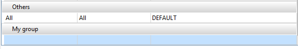
The groups are shown sorted in alphabetical order. The image below shows the ISD default settings.
The default entry in the Others group means that the setting DEFAULT will be assigned to all usages that do not occur in the other groups - independent of the part type.
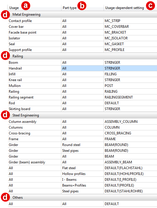
a) Usage, b) Part type, c) Assigned, usage-dependent setting, d) Group
As an example the settings displayed above mean the following for drawing derivation:
- Girder / All / ASSEMBLY_BEAM
For assemblies with the usage Girder, the configuration ASSEMBLY_BEAM will be used for the drawing derivation (from configuration), regardless of the assembly type.
- Girder / Round steel / BEAM(ROUND)
For elements of the part type Round steel and the usage Girder, the BEAM(ROUND) configuration will be used. If there is no usage assigned to the round steel, the DEFAULT configuration will be used.
- All / I - Beams / DEFAULT(I_PROFILE)
For I-beams - with or without assigned usage - the configuration DEFAULT(I_PROFILE) will be used.
- All / All / DEFAULT
For all assemblies and parts without an assigned usage and for which no default configuration is available, the DEFAULT configuration will be used.
Usage
Here you select the usage to which you want to assign a usage-dependent setting. The definition of new types of use takes place via the Catalogue Editor.
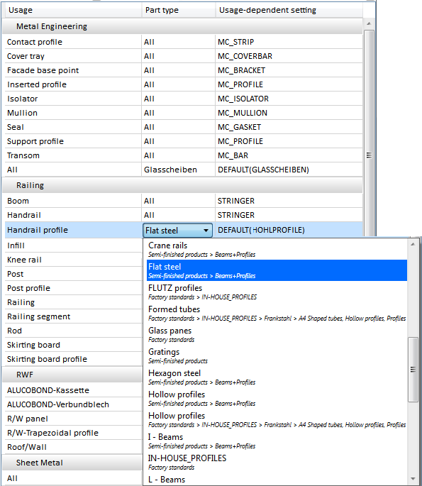
Part Type
If the usage assignment is to apply only to particular part types, you can specify in the corresponding field in the Part type column that the assignment is to apply only to assemblies, only to Sheet Metal parts, or only to particular catalogues.
In this way it is also possible to assign a configuration for the drawing derivation to parts and assemblies without an assigned usage.
Further information can be found in the Default Configuration for Assemblies without Usage topic.
For part types we differentiate between
- General
These are sheet metal or certain assembly types
- All
- Sheet Metal
- All assemblies
- Assembly
- Welded assembly (Workshop)
- Bolted assembly (Site)
- Glazing assembly
- Mullion assembly
- Transom assembly
- Glass assembly
- Insert assembly
- Planning grid
- Structure assembly
- Catalogue
These are beams which are defined in the HiCAD catalogues.
|
Part type |
Catalogue |
Part type |
Catalogue |
|---|---|---|---|
|
A1 Girder |
Factory standards > Factory beams > Frankstahl |
Glass panes |
Factory standards |
|
A3 Steel bar |
Factory standards > Factory beams > Frankstahl |
Hollow profiles |
Factory standards > Factory beams > Frankstahl > A4 Shaped tubes, Hollow profiles and Profiles |
|
B1 Commercial tubes, seamless |
Factory standards > Factory beams > Frankstahl |
Wood |
Semi-finished products |
|
B2 Commercial tubes, welded |
Factory standards > Factory beams > Frankstahl |
Factory beams |
Factory standards > Factory beams |
|
B4 Mechanical stress-resistant steel pipes |
Factory standards > Factory beams > Frankstahl |
Cold rolled sections | Semi-finished products |
|
B5 Precision steel pipes |
Factory standards > Factory beams> Frankstahl |
Crane rails |
Semi-finished products > Beams+Profiles |
|
B6 Hydraulic components |
Factory standards > Factory beams> Frankstahl |
L-Beams | Semi-finished products > Beams+Profiles |
|
Reinforced steel |
Semi-finished products > Beams+Profiles |
Beams+Profiles |
Semi-finished products Factory standards > Factory beams > Frankstahl > A4 Shaped tubes, Hollow profiles and Profiles |
|
Plates |
Semi-finished products |
Round steel | Semi-finished products > Beams+Profiles |
|
C-Beams |
Semi-finished products > Cold rolled sections |
Hexagon steel | Semi-finished products > Beams+Profiles |
|
C1 Pipes and Profiles |
Factory standards > Factory beams > Frankstahl |
Steel pipes | Semi-finished products > Beams+Profiles |
|
C3 Stainless steel bars |
Factory standards > Factory beams > Frankstahl |
T-Beams | Semi-finished products > Beams+Profiles |
|
Flat steel |
Semi-finished products > Beams+Profiles | U-Beams |
Semi-finished products > Beams+Profiles Semi-finished products > Cold rolled sections |
|
FLUTZ profiles |
Factory standards > Factory beams |
Square steel |
Semi-finished products > Beams+Profiles |
|
Formed tubes |
Factory standards > Factory beams > Frankstahl > A4 Shaped tubes, Hollow profiles and Profiles |
Voest Profile |
Factory standards > Factory beams |
|
Gratings |
Semi-finished products |
Z - Beams |
Semi-finished products > Beams+Profiles |
- User-defined
The Configuration Editor also supports the definition of own part types. These are offered for selection in the User-defined section. How to define own part types is xplained in the Usage Assignment for Own Part Types topic.
For instance, if the usage-dependent setting STRINGER should only be assigned to handrails of the type flat steel, then you have to select the entry Flat steel from the part types.
In this way, several assignment rows can exist. Identical usages are arranged in direct succession in the list, with the part type All coming last.
One example of this is the usage Girder.
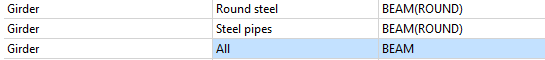
Here, the configuration BEAM (ROUND) is assigned to the usage Girder, if the part type is Round steel or Steel pipes. To all other part types, the configuration BEAM will be assigned.
Usage-dependent setting
Here you select the usage-dependent setting that you want to assign to the usage and to the part type. Choose the New usage settings from the selection box to define new usage-dependent settings.
Buttons
The buttons below the list have the following meaning:
|
New |
Click this button to define a new assignment. An empty row will be created within the current group. |
|
Delete |
Deletes the currently selected assignment. Click Apply to confirm the deletion. |
|
New group |
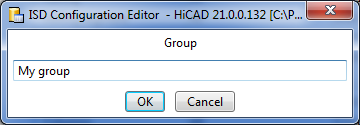
Usages can be neatly arranged into groups. To create a new group, click the New group button.
Enter the name of the new group and confirm with OK. The group will be added and an empty assignment row will be created.
Specify the new assignment and confirm with Apply. |
|
Apply |
Each change to the assignment list needs to be confirmed with Apply in order to take effect. |
To edit the list of assignments and define new usage settings, the user Administrator needs to be active.
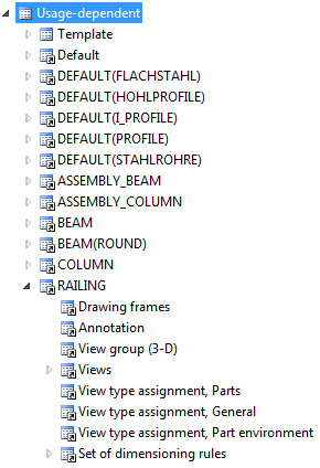
Usage-dependent
Here you can find the configurations for the various usages. in each configuration, the corresponding are defined.
A particular feature is the parameter Perform drawing derivation, which you can directly set for the chosen usage. You can use this parameter to specify for the current usage whether view groups are to be created in the drawing derivation process.
In addition, you can specify here
- whether usage-dependent drawing frames are to be created,
- how annotations are to be created,
- which views are to be created,
- how particular views, e.g. developments of Sheet Metal parts, are to be arranged,
- whether sectional views are to be created for attached parts, and
- how the dimensions are to be created in the different views.
Please note:
When using Civil Engineering Materials the execution of drawing derivation is not only dependent on the usage of the part but also on the settings in the column BIM_WSD. If BIM_WSD is set to “0” for a material of a part there will be no drawing derivation, irrespective of whether usage-dependent drawing derivation has been activated or not.
For further information click here.
Usage-dependent drawing frames
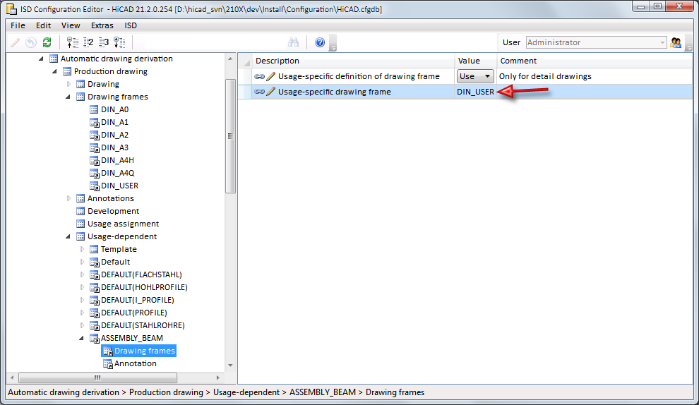
You can also specify usage-dependent drawing frames for detail drawings. Beneath Usage-dependent you can define, via the corresponding Drawing frames entry, the drawing frame for this usage.
To be able to use the desired drawing frame you need to change both parameters accordingly., e.g. as follows:

For the parameter Usage-specific drawing frame you need to enter the name A specified beneath Drawing frames in the structure tree, and not the name of the figure file B!
 Important:
- Usage-specific drawing frames can only be used for detail drawings. In such cases, the specified, usage-dependent settings of the uppermost BOM-relevant part will be read out. For workshop drawings (several parts in one drawing), the general setting for drawing frames specified at Automatic drawing derivation > Production drawing > Drawing frames will be read out.
- If you want to use usage-dependent drawing frames, one of the following options:
- To existing drawing,
- To external drawing or
- Detail drawings to external drawing
must be chosen as the Drawing target for the derivation.
- Beneath Sheet selection you must (!) select New sheet for each view groupor - if assembly, main and sub-parts should be put out in the drawing - New sheet for each assembly!
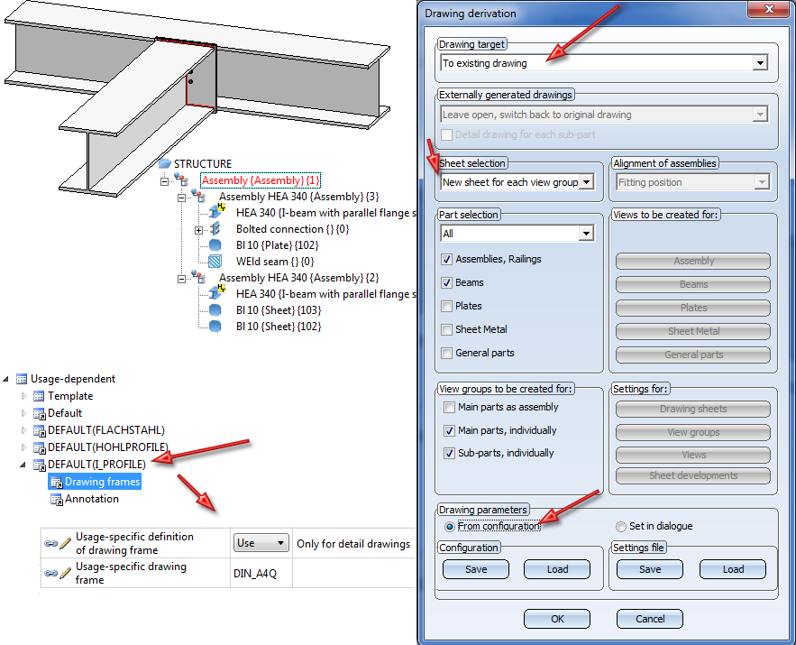
Example:
The image below shows a drawing consisting of two connected I-beams (HEA) and the associated part structure in the ICN. In the Configuration Editor, a Usage-specific drawing frame (DIN_A4Q) has been selected. When you perform a drawing derivation with the settings and options shown below, the drawing frame that was chosen in the Configuration Editor at DEFAULT(I_PROFILE), i.e. DINA4Q, will be used only for the detail drawings of the of the beams.
Dimensioning rules
Another special feature is the definition of dimensioning rules, as these are always loaded from the Configuration Editor - even if the Set in dialogue option is active in the Drawing derivation dialogue. If you do not want any dimensioning rules to be used, this must be changed accordingly in the Usage configurations, at ..> Automatic drawing derivation > Production drawing > Usage-dependent > NAME > Views, with NAME being the name of the corresponding Usage, e.g. RAILING. You can then use the Create dimensioning parameter to specify that:
- dimensioning rules are to be used,
- no dimensions are to be created, or
- conventional dimensioning are to be used, i.e. the settings specified in the Dimensioning Settings will be applied.
The definition of dimensioning rules for usages takes place at ..> Automatic drawing derivation > Production drawing > Usage-dependent > NAME > Set of dimensioning rules, with NAME being the name of the corresponding usage, e.g. RAILING.
Although the dimensioning rules can also be changed directly via the Configuration Editor , we recommend using the HiCAD Dimensioning Rule Editor for the easiest and most convenient handling.
Click here for an overview of the available dimensioning rules.

Derive Drawing • Drawing Derivation • Drawing Derivation: Dialogue Window • Configuration Management