General Information on Pipe Parts
Pipe parts are parts that you can integrate in a pipeline. They can be aligned and positioned with the help of guidelines.

Part insertion
Plant Engineering > New > Pipe parts 
Use the icons shown in the upper section of the window to select a part type that you want to insert in your drawing.
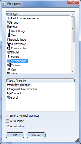
If the guideline mode is switched off, the Type of insertion area of the selection window will not be displayed. If the guideline mode is activated, you can choose, depending on the selected part type, between several types of insertion in the lower area of the menu window. After confirming the type of insertion, you can still revoke your decision with a right-click. The following options are available for almost all part types:
|
|
In flow direction
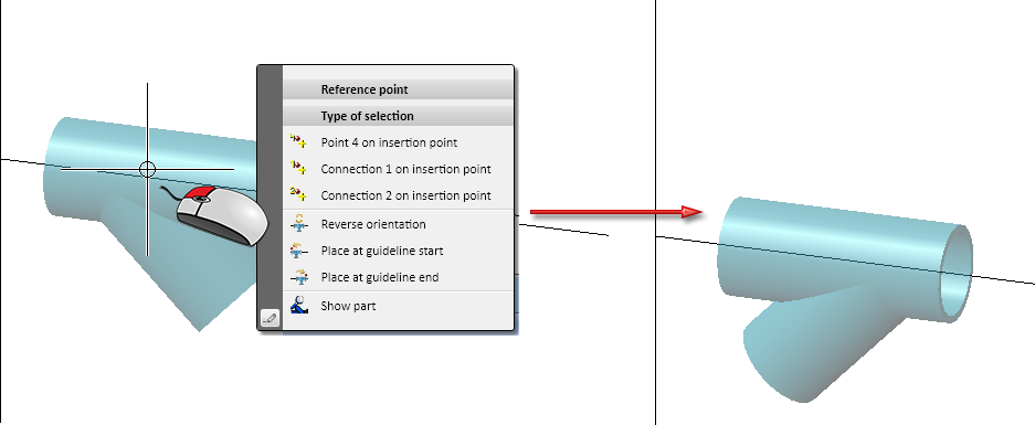
After selecting the part to be inserted you can change the orientation of the part if desired. To do this, right-click and choose Reverse orientation Furthermore, you have the option to place the part directly at the start or the end of a guideline. For this you use the options Place at guideline start
|
|
|
Against flow direction
Here, too, the orientation of the inserted part can be reversed, as described above. |
|
|
Connect
If the Show search criteria if part search unsuccessful checkbox has been activated on the Part search tab of the Plant Engineering Settings, the search criteria you have used will be shown after an unsuccessful or aborted part search. |

 in the


The selected insertion option remains valid until another part is selected. HiCAD then returns you automatically to the Part in edge direction option. Depending on the part and guideline mode selected, HiCAD offers further insertion options. In the following sections, we describe these options for individual part types.
Via the classification that is assigned to the type of tze selected part, HiCAD looks for the information of corresponding parts in the part data source (database or catalogue) and outputs a result list. The length of this list depends partly on respective selection sets.
The pre-selection can be determined by the pipe class of the selected pipeline and/or the content of the pre-selection mask. The type of pre-selection or whether pre-selections are made can be specified in the Plant Engineering Settings.
 Please do not delete the result list for link sources via the context menu, as important VAA files would be lost as well as the records! The sub-chapter Variant AutoSync provides a detailed description of how to delete Variants from the database.
Part insertion via P+ID
Plant Engineering > New > Pipe parts >via P+ID 
If the layout plan has been linked to a P+ID, or if your drawing contains referenced 3-D assemblies linked to P+IDs, you can also determine components via the corresponding P+ID symbol.
Layout plan <->P+ID link
If you want to process a Plant Engineering layout plan while the corresponding P+ID has been loaded, proceed as follows:
- You need to activate the required pipeline before a pipe part can be inserted.
- When you click the via P+ID option in the menu window, the sheet of the open P+ID appears on your screen. The symbols representing parts existing in the layout plan are highlighted.
- Use the cursor to select the symbol to which the corresponding part should be assigned for insertion in the layout plan. Select END to cancel the function and return to the layout plan.
- To check symbol data, respond with Yes to the query Do you want to see symbol data? HiCAD displays the content of the symbol data mask. If a part has been assigned to the symbol, you can click Part data to display the contents of the associated record. If no parts have been assigned, HiCAD issues an appropriate message.
If you click OK in the dialogue box showing dialogue data, or if you click No because you do not want to see symbol data, you are returned to the layout plan, whereby the part is now ready for insertion. If the part is already inserted, HiCAD issues an appropriate message, and highlights the part.
If no part has been assigned to the symbol, HiCAD looks for a suitable part. This search is based on the part ID contained in the symbol data mask, (in the case of pipe parts, it is also possible to find parts via the pipe class assigned to the pipeline and the nominal diameter), as well as the symbol name (if the appropriate setting has been made in the P+ID). You can then select the required part in the result list that appears on your screen.
When you insert the part, its item number is automatically entered in the data mask of the corresponding symbol in the P+ID, i.e. the P+ID symbol is assigned to the part.
If a part for the selected symbol has already been inserted in the layout plan, HiCAD will display an approprioate message and the part will be highlighted in the drawing.
Referenced assembly <-> P+ID link
If the active pipeline does not belong to a referenced 3-D assembly, and one of the P+IDs linked to the assembly has been loaded, you have the option to determine parts via their corresponding P+ID symbol. Activate the corresponding pipeline beforehand. The further procedure is identical to that for the Layout plan <->P+ID link.
 Please note:
- When you insert parts via the P+ID, you can transfer P+ID symbol dialogue texts of the symbol data masks to assigned, user-definable system attributes of the 3-D part. This assignment is defined via the P+ID attribute assignment tab.
- After insertion of a pipe part or a component using the Determine via P+ID option, the P+ID viewer window will be redisplayed immediately, to enable the selection of the next symbol.
Further notes
- HiCAD only recognises a pipe class assigned to the active pipeline as a pre-selection, if the pre-selection option Via pipe class or Via pipe class and pre-selection mask in the Part selection tab of the Plant Engineering Settings window have been set.
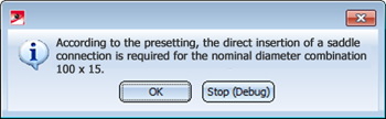
- If the Use presettings for placing of parts on branching points checkbox on the Part placing on branching points tab of the Plant Engineering Settings dialogue is active, HiCAD will first ask for nominal diameters when you try to place a T-piece, a saddle connection or a straight pipe on a branching point, if these nominal diameters are not already given by the pipeline (or guideline). It will then be checked which definition applies to the current nominal diameter combination. If the part type selected for part insertion does not match the valid definition, a corresponding message will be displayed and the function will be cancelled. e.g.
- The options Ignore nominal diameter , AutoFlange and AutoReducer at the bottom of the dialogue window correspond to certain Plant Engineering settings. Activating or deactivating these options in the dialogue window has only temporary effect. After execution of the function, the original Plant Engineering settings will apply again.
- Necessary reducers will be automatically inserted into pipelines if the following conditions are met:
- The AutoReducer option is activated.
- A nominal diameter has been assigned to the active pipeline, or a nominal diameter has been defined for the guideline onto which the part is to be placed.
- The Ignore nominal diameter option has been set.
- An individual part (no straight pipe) the nominal diameter of which deviates from that of the pipeline (or the guideline) is inserted interactively.
The AutoReducer option does not take effect for options within the Pipe parts function used for automatic, multiple part insertion, e.g. T-piece, Set all.
- When using the Pipe parts functions to place parts on pipelines you can automatically take welds gaps into account. The gaps between the parts will be immediately visible in the layout plan. On the Weld gap tab of the Plant Engineering Settings dialogue you can specify whether weld gaps are to be taken into account, as well as the procedure for the determination of the gap width.
- If you use the HiCAD Catalogue as part data source for part selection, please note the following: In the Plant Engineering catalogue supplied with HiCAD 2013, the sub-catalogue Gauge has been re-named to Gauge parts (catalogue alias name), and the assigned part type ID has been changed to 5920010 (catalogue name).
- Parts with only one "genuine" connection still require two named isolated points (Designation: ! and 2) to enable them to be auto-aligned correctly. To prevent Point 2 from being falsely interpreted as a connection in the isometry, the attribute ANSCHLUSSART2 (CONNECTION2) needs to be set to the value 0.
- In case of multiple insertions of the same part (e.g. a valve) on different guidelines, the selected insertion direction (In flow direction or Against flow direction) as well as the selected reference point (Connection 1, Connection 2 or, e.g. in the middle between them) will be retained.
In connection with the Ignore diameter option we also recommend reading the information given in the chapter Automatic Adjustment of Nominal Diameter Condition.

Pipe Parts (PE) • Part Selection - Catalogue or Database (PE)