The image below shows a contour that is to be used in different sizes for the creation of bore patterns. It can either be created and parameterized as a 2-D part or as a planar sketch.
Case 1: Parametrized 2-D part (File format: .DCF)
Case 2: Parameterized sketch (File format: .KRA)

Case 1: Parameterized 2-D part (File format .DCF)
Step 1: Create the 2-D part
- Create an empty 2-D part, e.g. MUSTERBSP.
- Draw a square with the dimensions 40x40, and fillet its corners with a radius of 4.
- On the 2-D Geometry tab, choose Tools > New point
 and place an isolated point in the centre of that rectangle.
 - Move the 2-D part in such a way that the isolated point is located in the absolute zero point (0,0).
Step 2: Derive the 2-D HCM model
- Open the Information tab and delete the variables store via 3-D, Further > Var.
 > Delete variables
  .
. - Open the 2-D Part tab.
- There, choose 2-D HCM Constraints > Fix > Parallel
 to determine the parallelism constraints. After calling the function, first identify the two vertical lines, and then the two horizontal lines.
 - Then, use the Tangential
 function to assign the same-named positional constraint to the elements: Identify, one by one, a line and an arc, so that you end up having a total of 8 tangential constraints.
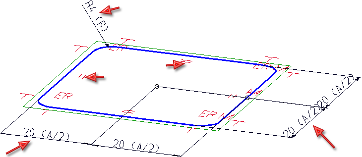
- Now, assign the dimensional constraints shown below (radius, horizontal distance, vertical distance). Instead of making a value input, right-click and enter the formula a/2 and R, respectively. Choose a=40 and R=4 as start values.
- Since all fillets are to be identical, choose Distance > Equate radius
 for the non-dimensioned fillets.
 - Fix the isolated point with the positional constraint Fix
 .
. - Save the HCM model with the function Edit > Without database
 , e.g. with the name PATTERNEXP. Select the HiCAD directory KATALOGE/WERKSNORMEN/MUSTERBOHRUNGEN as the target directory.
Expand the MUSTERBOHRUNGEN catalogue
- Start the Catalogue Editor by double-clicking the CATEDITOR.EXE in the HiCAD EXE directory.
- Open the Bore patterns catalogue. Choose Extras > Table > New and create a new table for the bore pattern, e.g. PATTERNEXP.
- Select the category 2-D patterns. Exit the dialogue window with OK.
- The new table contains the columns ID, MOD, STATUS and BZ.
- Now, add further columns by right-clicking the header of the BZ column and selecting New column.
|
Designation |
Data type |
Comment |
|
|
NAME |
Text |
Path of HCM model |
|
|
A |
Float |
Lateral length of square |
|
|
R |
Float |
Fillet radius |
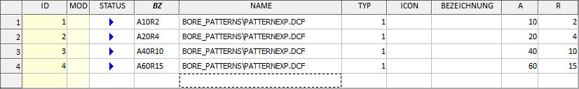
- Create the following data records:
- The new bores will now be available in HiCAD.
Case 2: Parameterized sketch (File format: .KRA)
Step 1: Create the sketch
- Choose Sketch > New > Sketch
 and create a new sketch.
 - Draw a rectangle of the size 40 x 40 with the Sketch > Draw > Rectangle
 function.
 - Fillet the corners with the Sketch > Process > Fillet
 function (Radius: 4).
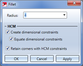
Depending on the settings in the Sketch HCM, certain constraints will be automatically entered.
- Open the Sketch tab and choose New > Point . Place an isolated point in the centre of the square. Call the New point number
 in the pull-down menu of the Point function to assign the point number ! to this point. Via this point number you can influence the fitting point during insertion of parts and assemblies.
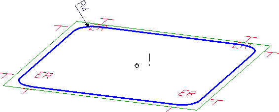
- Then, assign the remaining HCM constraints.
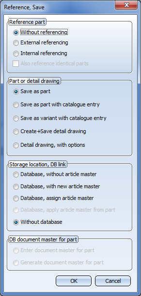
- Save the sketch with the Reference part, Save, Detail drawing
 function, e.g. with the name PATTERNSKT, to the HiCAD directory KATALOGE/WERKSNORMEN/MUSTERBOHRUNGEN.
Step 2: Expand the MUSTERBOHRUNGEN catalogue
- Start the Catalogue Editor by double-clicking the CATEDITOR.EXE in the HiCAD EXE directory.
- Open the Bore patterns table. Choose Extras > Table > New and create a new table for the bore pattern, e.g. PATTERNSKT.
- Select the category 2-D patterns. Exit the dialogue window with OK.
- The new table contains the columns ID, MOD, STATUS and BZ.
- Now, add further columns by right-clicking the header of the BZ column and selecting New column.
|
Designation |
Data type |
Comment |
|
|
NAME |
Text |
Path of KRA file |
|
|
A |
Float |
Lateral length of square |
|
|
R |
Float |
Fillet radius |
- Now, create the following data records:
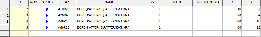
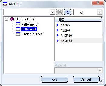
- The new bores are now available in HiCAD.

Bore Patterns (3-D) • Standard Processings (3-D) • Variable Through Holes (3-D) • Repeated Insertion of Standard Pats (3-D)