Planar Sketch
Sketch > New > Sketch 
Sketches are 3-D parts which lie in a plane and have free edges. They are, for instance, used for the creation of extruded solids, bores and subtractions, as well as for c-edge sweeps, sectional views and many other functions.
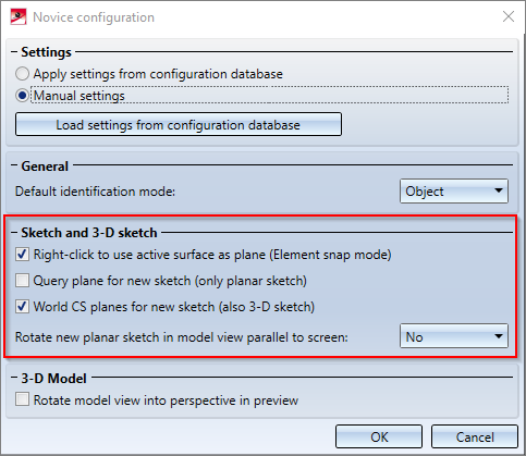
To execute the function, you need to determine the plane in which the sketch is to be drawn. This determines the part coordinate system of the 3-D sketch. How this plane is determined depends on the settings in the Novice configuration dialogue that you open via Drawing >  Extras
  > .... Also read the notes given in the Novice configuration topic of the HiCAD Basics Help.
ISD default setting
If the Query plane for new sketch (only planar sketch) checkbox is inactive (default), the sketch is drawn in the active sketch/processing plane. If no such plane exists, the XY-plane of the world coordinate system will be used as the sketch plane.
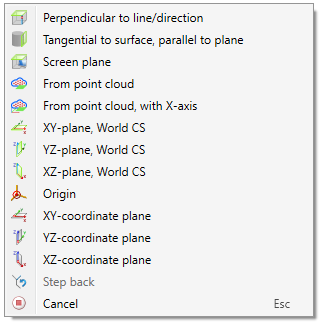
If the checkbox is active, then HiCAD explicitly requests that the plane be determined. You can use any points, edges, surfaces or processing planes. In addition, you can call a context menu with further functions by clicking the right mouse button.
This procedure is identical to that for creating processing planes.
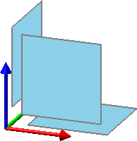
If the checkbox World CS planes for new sketch (also 3-D sketch) is also active in the Novice configuration dialogue window, you can simply select one of the default planes displayed as a preview with the cursor or call the context menu shown above with a right-click.
HiCAD creates a new main part called SKETCH with the geometry type Part with free edges. The part type is Sketch  .
.
A sketch can contain the following sketch elements:
- Polylines,
- Polygons,
- Circle,
- Circles,
- Ellipses,
- Curves,
- Special elements such as straight lines, projections, hyperedges etc.
- Auxiliary geometries.
Use the functions of the Sketch tab to draw the sketch. Please note that the sketch elements are always drawn in the sketch plane. The sketch plane is automatically placed in the active processing plane (unless nothing different was specified in the Novice configuration). If no processing plane is active, the sketch plane is placed in the XY-plane of the active coordinate system. If you want to use a different plane as sketch plane, use the plane functions that you access via Sketch > New.
Clicking opens a pull-down menu with the following functions:

|
Sub-part Select this function if you want to insert a sketch as a sub-part. |

|
Use this function to convert 2-D parts into planar sketches. |
![]() Please note:
Please note:
- The representation of sketches depends on their purpose.
- In the case of 3-D objects derived from sketches, HCM dimensional constraints assigned to the sketch are adopted as parameter dimensions. This applies, for example, to extruded solids or revolved solids as well as to bores, subtractions etc.
- Sketches have priority over congruent solid edges. In other words, if the cursor is in the vicinity of two exactly overlapping edges, and one of these edges belongs to the active drawing, this sketch edge will always be marked and identified when you click on it. This behaviour is supported both in shaded views and in glass body representations.
- The function for planar sketch creation is also available in the context menu for parts and in the context menu for drawings.
Please also read the notes on purposes and representation of sketches.

