Exploded view> New/Change > Activate exploded view 
Use the Exploded view function to convert the active view into an exploded view. if the active view is already an exploded view, the Exploded view mode will be activated. In this mode you define the desired displacements and rotations.
Define exploded view
To create a view with an exploded layout for a drawing or an assembly of a drawing, proceed as follows:
- Load the desired drawing.
- Create a new view for the exploded layout, e.g. Exploded view_1.
- Activate this view and call the Activate exploded view function.
This activates the Exploded view mode, as can be seen by the green symbol at the top left corner of the drawing area:
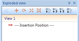
The Exploded view docking window will be opened automatically. There you can create a new exploded view.
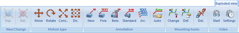
- Now you can choose the desired transformation (motion type). Possible are:
The corresponding dialogue window will be displayed, e.g.:
![]()
The operation is largely similar for all transformations; it differs only in the transformation parameters.
Selection of the parts to be transformed
In the first step you select the parts to be transformed. By default, the parts list at the top of the dialogue window contains the part that is active when you call the function. You can remove this part from the list if required. To do this, right-click the part and select Remove element(s) from list. Multiple selections are also possible.
To select the required parts, click on the  symbol and then identify the parts in the ICN or in the drawing. If a part is already in the parts list, it will be removed from the list when it is identified again.
As long as the part selection is active, the displayed context menu can be opened by right-clicking on the drawing area.

With the Parts in rectangle function, you can then also select all parts within a rectangle.
All parts listed in the parts list are highlighted in the drawing.
When selecting the parts to be transformed, the immediate superordinate part to a part can also be selected. To do this click the part with the left mouse button and hold it down. Then press the right mouse button additionally. HiCAD then searches for the next superordinate part and marks it. If necessary, continue the search by pressing the right mouse button again.
Enter the transformation parameters
In the next step you specify the parameters for the desired transformation:
Whenever you need to select an axis or a direction, the following applies. If the Select direction/axis field is coloured, you can determine the direction or axis directly. If this is not the case, click on the  symbol to select the direction or axis. The direction/axis can be determined by selecting two points, by selecting an edge or by selecting a surface. In the case of a surface, the direction is determined by its surface normal.
Alternatively, you can use the functions of the context menu, which you activate with a right-click, to determine the direction/axis:
|
Concentric, about an axis |
|
|---|---|
|
|
Origin
|
|
|
X-axis |
|
|
Y-axis
|
|
|
Z-axis
|
|
|
Step back
|
|
|
Cancel
|


In the lower area of the dialogue window, you can determine for each transformation whether mounting tracks are to be entered in the drawing that mark the course of a transformation. The following options are available:
- No track
- One track for all parts
Only one mounting track for the parts chosen for a transformation will be created. By activating the point input field and a subsequent determining of a point, you can specify the start point of the mounting track. Otherwise, the start point will be placed automatically iin the centroid of the first part of the selection list. - One track for each part
One mounting track will be created for each transformed part.
Depending on the selected option, a preview of the mounting tracks is displayed in the drawing. The parameters defined with the Exploded view > Mounting tracks > Def  function and/or via the Configuration Editor at Drawing > Views > Exploded view are used to display mounting tracks.
If the Apply immediately checkbox is active, the transformation will be immediately accepted - as shown in the preview - and entered into the explosion log, i.e. you do not have to click the Apply button. If further parts are selected immediately afterwards - without changing the other settings - the same transformation is carried out immediately for these parts without the parts appearing in the selection list.
If the checkbox is not active, then use buttons. If you click OK the transformation will be accepted and the dialogue window is closed. If you click Apply the current transformation will be accepted. Unlike OK, the dialogue window will not be closed here, so that further transformations can be defined. If you click Cancel the dialogue window will be closed. Transformations that have not yet been adopted are lost.
Each applied transformation will be logged in the Exploded view docking window.
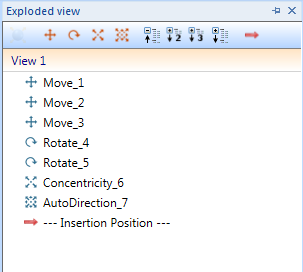
Exploded views can be subsequently edited via this log.
 Please note:
- All functions for creating and editing exploded layouts can be found on the Exploded view Ribbon tab.
- Exploded views are indicated in the Views window of the ICN by the symbol.
- The transformations obtain consecutive numbers, e.g. Move_1, Move_2, Rotate_3, Concentricity_4 etc.
- Multiple exploded views can be created for one model.
- Exploded views can also be copied - including all exploded view data, i.e. the movements and rotations.
- Changes to the model also affect already existing exploded views.
- Sectional views, detail views and cut-outs, too, can be converted into exploded views.
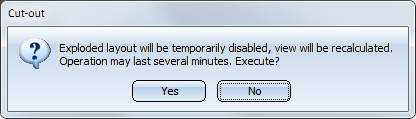
- In an exploded view you can also create and edit cut-outs. For this purpose the exploded view will be temporarily deactivated. A corresponding message will be displayed, with the option to cancel the process:
- As soon as parts are changed that belong to an exploded view, the exploded view is marked as invalid. This is indicated by a red cross in front of the view, similar to sectional and detail views. To update the exploded view, select the function Views > Edit > Update
 .
.

Delete exploded view
Exploded view > New/Change > Delete exploded layout in active view 
Use this function to delete an exploded view. This means that all transformations defined for the exploded view will be deleted, and the view is converted back to a "normal" view.
Cut-outs that were created in the Exploded view will be retained.
You can also find this functions in the context menu for views at Representation > Others.
